1 Introduction
This article refers to the address: http://
Detection technology is one of the indispensable key technologies in the fields of electronics and communication, so the detection circuit is also very important in these fields. The quality of the detection technology directly affects the separation and extraction of the signal. In the television receiver, the video detection is located between the intermediate stage and the pre-view, and the video signal is detected from the image intermediate frequency signal and the auxiliary intermediate frequency signal is secondarily mixed. It can be seen that the quality of the detection link directly affects the performance of the whole machine. With the development of TV technology, the enhancement of TV functions and the improvement of TV performance requirements, the original detection technology is difficult to meet the requirements of TV for video detection. Therefore, more advanced detection technology must be used instead of the original detection method.
Early video detection uses the unidirectional conductivity of the diode to extract the envelope from the amplitude modulation wave to obtain the video signal. In the mixing, the nonlinearity of the diode is used, and the 38 MHz local oscillator and the 31.5 MHz audio intermediate frequency are used for mixing. Take out the second audio intermediate frequency signal of 6.5 MHz. Synchronous detection removes two chromatic aberrations from the balanced amplitude modulation wave to complete the separation of Fu and Fv. Although this kind of detection is better than the former one, there are still some shortcomings, and the phase-locked loop detection better overcomes the first two shortcomings and is widely used in modern video detection.
2 phase-locked loop synchronous detection
2.1 Synchronous detection principle
As shown in Fig. 1: after the video signal is selected, amplified and frequency-converted by the high-frequency tuner, the obtained 38 MHz image intermediate frequency and the 31.5 MHz audio intermediate frequency are sent to the image, and then amplified and sent to the video detection circuit. Since the video detection uses synchronous detection, the required synchronous switching signal is obtained by limiting the amplitude of the image intermediate frequency signal under the action of 38 MHz detection, thereby completing the detection. The output FBAS (color full TV signal) and SIF2 (second audio IF signal) are sent to subsequent related circuits.
2.2 Problems with synchronous detection
(1) When the local oscillator frequency of the high-frequency tuner shifts, the intermediate frequency deviates from 38 MHz, and the demodulated signal will be disturbed and attenuated, resulting in distortion. Although this distortion can be corrected by the AFC circuit in the middle, if the AFC circuit has a problem, it cannot be solved at this time.
(2) When over-modulation occurs in the image intermediate frequency, the amplitude of the switching signal is insufficient, so that the distortion cannot be demodulated or demodulated. This problem cannot be solved by the AFC circuit.
It can be seen that there are some shortcomings in the synchronous detection. To solve the above problems, the detection circuit must be redesigned to overcome the shortcomings of the detection circuit.

3 phase-locked loop video detection
3.1 phase-locked loop circuit
Phase-locked loop video detection is also called PLL (Phase Locked Loop) video detection. The core part is the phase-locked loop circuit: the phase-locked loop is essentially an automatic phase control system. As shown in Figure 2, the circuit consists of a voltage-controlled crystal oscillator 'VCO, 90° phase shift, APC detection, low-pass filtering and switches. There are two inputs to the APC, one for the reference signal from the 38 MHz image IF and the other for the output signal from the VCO for comparison. The two signals are compared in frequency and phase within the phase detector APC and the compared difference is converted to an error voltage output. After the error voltage is low-pass filtered, a control voltage is obtained to control the VCO so that its frequency and phase are close to the reference signal. Once the loop is locked, the frequency and phase of the VCO output signal must be equal to the reference signal frequency and phase, and can vary with the conversion of the reference signal. The low-pass filter is designed to filter out unwanted high-frequency signals and other outputs in the phase detector output signal, improving loop performance.

3.2 Phase-locked loop detection principle
As shown in FIG. 3, the circuit adds a lock detection circuit, the input signal is color full, and the output signal is sent to a low pass filter and a switch circuit to determine whether the loop is locked. The output signal is sent to the video detection circuit as a 38 MHz switching signal.
In view of the characteristics and existing problems of the first two kinds of video detection, the detection circuit mainly improves the following two aspects, and completely solves the shortcomings of the above-mentioned detection circuit:
(1) For the normal synchronous detection, the switching signal of this circuit comes from the image intermediate frequency. When the image intermediate frequency deviates from 38 MHz and the AFC has a problem and cannot correct the offset, the 38 MHz off signal of the detection circuit comes from the voltage controlled oscillation. The VCO, rather than the IF from the 38 MHz image, is therefore independent of the image content. Even if the local oscillator frequency of the high frequency tuner shifts and the AFC circuit has a problem, or the image IF signal is overmodulated, the switching signal can be accurately 38 MHz, so that the demodulated signal does not cause distortion. At the same time, the VCO of the detection circuit can still send a switching signal of sufficient amplitude to the detector. The external 38 MHz of the VCO is used to determine the VCO oscillation frequency, which is no longer part of the limiting amplifier. Utilizing the mid-week can change the oscillation frequency and finally lock the loop, so that the aforementioned problems are well solved.
In order to make the 38 MHz switching signal in phase with the 38 MHz image IF, a phase-locked loop must be used. There is an APC circuit in the loop, which sends the VCO signal to the APC as a comparison signal through 90° phase shift, and sends the image intermediate frequency to the APC as the reference. Both compare the frequency and phase in the APC circuit, and the comparison results output an error voltage proportional to the frequency difference and phase difference between the two. The voltage is low-pass filtered to obtain the APC DC control voltage, which is then applied to the VCO to correct the frequency and phase of the VCO until the two input signals fed to the APC have the same frequency and phase difference of 90°. In this way, it can ensure that the two input signals of the video detection are in phase with the same frequency, realizing true synchronous detection.
(2) A lock detector is specially set on the circuit, and its main function is to ensure loop lock. Whether the loop is locked or not is determined by detecting the amplitude of the color after detection. If the full amplitude of the color is small and there is interference, the lock detector outputs a control signal to the switch to change the low-pass time constant until the loop locking.
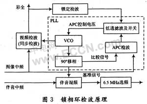
Setting the 90° phase shift is a requirement of the APC detector circuit. When the two input signals differ by 90°, there is no error voltage output. In addition, after the VCO signal is phase shifted by 90°, the mixing circuit is also sent to mix with SIF1 (first sound intermediate frequency) to generate a second audio intermediate frequency of 6.5 MHz. Since the 38 MHz required for mixing is not from the image intermediate frequency but from the VCO, there is absolutely no interference with the 38 MHz amplitude modulation wave on the 6.5 MHz signal, so that the interference of the image to the sound is completely suppressed.
4 Conclusion
The detection circuit is an important part of the TV circuit, and its advantages and disadvantages directly affect the processing effect of the entire TV set. It is developed along with the development of TV technology. Phase-locked loop circuits are commonly used circuits in electronic devices and have a wide range of applications in new large-screen color television sets. Practice has shown that it is a good way to detect and achieve good results.
Multi Function Flashlight,Tool Kit Flashlight,Flashlight with Swiss Army Knife
Asia Leader Import & Export Co., Ltd. , http://www.nbflashlight.com