Thermal resistance definition: The ratio of the temperature difference across the heat flow path to the power dissipated on the channel.
LED thermal resistance definition: Rth j-sp: Thermal resistance from PN junction (j) to solder joint (sp). Unit: °C/W or K°/W
Detailed explanation: When the heat conduction steady state is reached after the LED is lit, the power difference between the temperature of the chip pn junction and the temperature of the connected bracket or the aluminum substrate is called the thermal resistance Rth. It is °C/W. The lower the value, the faster the heat in the sheet is transferred to the holder or aluminum substrate. This helps to reduce the temperature of the pn junction in the chip, thereby extending the life of the LED.
Influencing factors:
1. It is related to the structure and material of the LED chip itself.
2. The thermal conductivity of the material used for bonding with the LED chip and the quality of the bonding are related to whether the adhesive has good thermal conductivity, whether it is insulated or thermally conductive, or directly connected by metal.
3. What kind of material is the heat sink made of? It is made of copper with good heat conductivity, or aluminum, and it has a direct relationship with the heat dissipation area of ​​copper and aluminum.
4, select a certain material and control related technical details, you can reduce the thermal resistance of the LED, thereby improving the life and performance of the LED.
Thermal resistance test:
According to the LED chip pn junction temperature rise 10 ° C, the wavelength will drift 1 ~ 2nm, or when the pn junction temperature rises 10 ° C, the light intensity will drop by 1%, according to this law can be measured how much the pn junction temperature rises .
The 13th Research Institute of China Electronics Technology Group manufactures a reliability analyzer for the NC2992 semiconductor device, which can be used to test thermal resistance. This instrument works by using a semiconductor device with a good linear relationship between the forward voltage and temperature of the LED at a constant current (see Figure 1 for the test wiring diagram). The relationship between the input voltage and temperature can be approximated by the following formula:
• VT j=VT o +K(Tj-To) (1)
Where VT j and VT o are the input voltages of Tj and To, respectively; K is the temperature coefficient of thermal sensitivity, which is related to the substrate material of the chip, the structure of the chip, the package structure, the wavelength of the light, and the like. Thermal resistance is the ratio of the temperature difference along the heat flow path to the power dissipated on the channel. For LEDs, the thermal resistance generally refers to the thermal resistance from the LED core to the heat sink.
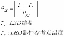
The thermal resistance calculation formula can be expressed as:
• Rt h =( Tj-Tx)/P (2)
• where Tj is the LED junction temperature measured after applying a heating power pulse of size P; Tx is the temperature on the heat sink aluminum substrate.
According to Fig. 1, a certain heating power pulse (constant current IH) is applied to the LED to be tested, and the pn junction of the LED to be tested is heated. Compare the amount of voltage change measured under a constant current IM bias before and after the application of a constant current pulse. Under the premise that the measured junction temperature of the LED is the same as the temperature of the heat sink before the test, the temperature of the heat sink is measured by the temperature detecting device, thereby obtaining the initial junction temperature of the LED to be tested.
• Since the pn junction temperature rise is linear with its forward voltage change under forward current IM, the correlation coefficient K is the device's thermal temperature coefficient (mV/°C). By this temperature coefficient of temperature, the junction voltage change amount ΔVF before and after the application of the power constant current pulse can be converted into the corresponding junction temperature change amount under a constant bias current IM. Equations (1) and (2) can be rewritten as equation (3):
• Rth = ΔVF/K•P (3)
• As shown in Figure 1, first the switch is set to "1", the LED under test is injected with a constant current IM, and its forward voltage VF1 is measured. Then the switch is switched to "2", and the measured LED is injected with a constant current IH to increase the junction temperature. After a certain time, the switch switches to "1" again, and the forward voltage VF2 of the LED is measured under IM. Finally, the thermal resistance can be calculated.
Edit: Sophy
2Pans Buffet Server,Buffet Server Warming Plate,Buffet Server Warmer,2Pans Buffet Server Warmer
Shaoxing Haoda Electrical Appliance Co.,Ltd , http://www.hotplates.nl