Since the advent of the iPhone in 2007, annual sales of inductive capacitive touch screens have increased 100-fold, and there is no sign of slowing down. This article describes many of the design and application challenges that must be faced when integrating an inductive capacitive touch screen into a single device, with an emphasis on the importance of the controller's signal-to-noise ratio.
This article refers to the address: http://
Introduction Since the advent of the iPhone in 2007, the range of applications for inductive capacitive touch screens has continued to expand. Despite this, the integration of inductive capacitive touch screens into devices still presents significant challenges, especially in environments where liquid crystal displays (LCDs) and peripheral devices are interfering and noisy. One of the effective solutions is to use a high signal-to-noise ratio (SNR) touch screen controller to combat noise. A high SNR controller will have other advantages, as described in more detail below.
SNR is defined as the power ratio of the signal (useful information) to the noise (unwanted signal). If the signal and noise are measured at the same load, the SNR can be obtained by calculating the square of the root mean square (RMS) of the amplitude. The value of the power ratio (PS/PN) is usually large and is usually described in logarithmic (dB). The SNR can be expressed as:
SNRdB = 10log10(PS/PN) = 10log10(RMSS/RMSN)2= 20log10(RMSS/RMSN)
A high SNR means that the measured signal strength is higher than the background noise.
Overall Touch Performance The overall touch performance is determined by two devices: the touch screen sensor and the touch screen controller. There are many types of touch screen sensors, and their names indicate their shapes and structures, such as triangles, diamonds, snowflakes, bars, and so on. For example, "diamond" is a diamond-shaped grid structure, and "bar" is a grid of rows and columns, like a city street. Some sensor types use one layer of ITO, while others require two or three layers, depending on the desired system performance and touch screen controller chip.
The touch screen sensor style and layer structure ("stacking") is typically determined based on the touch screen controller structure to maximize SNR. For example, in a diamond pattern with a single layer of mutual capacitance with crossover (bridge), the distance between the touch screen surface and the X and Y layers of the ITO is the same, which reduces the gain error and makes the SNR of the rows and columns very close. However, it is still necessary to add a shield to prevent the sensor from being disturbed by LCD noise. Using a high SNR touch screen controller can reduce the cost of the touch screen sensor, relax design constraints, and use more styles and layer structures. As will be discussed below, the high SNR touch screen controller can also provide additional benefits such as easier access to the touch center, reduced sensitivity of the touch screen to ambient noise, and the use of gloves or pointed pencils.
Controller architecture self-contained and mutual-capacity 1 are two main capacitive touch screen sensing detection technologies. The characteristics of self-capacitance and mutual capacitance are summarized as follows:
Self-contained ï¬ Early technology still in use today.
ï¬ Limited to “ghost points†(incorrect touch locations relative to real touch locations), usually one touch or two touches.
ï¬ Diamond shapes are the most common.
ï¬ Poor LCD noise suppression.
ï¬ Simple, low-cost controller.
Mutual capacity ï¬ A new generation of designs that are capturing the market.
ï¬ True two or more touches.
ï¬ Higher precision.
ï¬ Sensor style design is more flexible, which helps maximize SNR.
ï¬ Better noise suppression.
ï¬ More complex, high cost controllers.
Many applications require only one or two contacts, so the self-contained solution is more attractive, especially when the touch position of the user interface is controllable to eliminate "ghost points". The typical SNR of a self-contained solution exceeds 30 dB, and it is usually necessary to add a shielding layer between the LCD and the bottom of the touch layer of the sensor, which increases the cost and reduces the display brightness.
Other techniques can be used in a self-contained scheme to further increase the SNR. This includes (a) increasing the number of samples per channel; (b) increasing the sensor drive voltage, which increases the amplitude of the signal at a fixed noise (such as noise from the LCD); (c) sampling at different frequencies to avoid fixed frequency interference, Such as avoiding 60Hz (this is called "frequency jitter"). However, this technique usually reduces the frame rate and increases power consumption, both of which are undesirable.
As can be clearly seen from the above discussion, in order to maximize SNR and support two or more points of touch, mutual capacitance is the most promising sensing detection technology. The system block diagram of Figure 1 summarizes the implementation of the mutual capacitance method, that is, adding one excitation signal to one pole of the touch screen sensor capacitor and the other pole to the analog front end (AFE) of the touch screen controller, the output of the AFE is converted into The digital format is further processed in a digital signal processor (DSP).
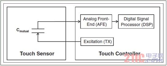
Figure 1. Block diagram of a mutual-capacity system.
Design Challenges When integrating capacitive touch screen sensors into touch devices, there are many technical challenges. The conditions described below can all benefit from a high SNR touch screen controller.
Sensor Layer Design: There are a variety of touch screen sensor layer structures today that correspond to different materials, thicknesses, performance and cost requirements. as shown in picture 2. Whether a single layer or a multilayer substrate, "up" or "down" architecture, variations in the thickness of the X and Y layers, changes in the thickness of the transparent adhesive (OCA), and other factors can affect the amplitude of the signal produced by the sensor. Since the high SNR touch screen controller can handle wide dynamic range touch screen sensor signals, the effects of structural differences can be diminished. This gives the designer more freedom to choose the sensor layer structure.
Thick Shield: Some applications, such as bank ATMs, may require a thick glass cover to prevent the display from being damaged. However, the thick glass cover will reduce the intensity of the touch signal and reduce the accuracy of the touch position detection. This is because the distance between the finger and the touch screen sensor becomes larger, resulting in a larger capacitance range, lower signal amplitude, difficulty in determining the precise touch position, and wearing gloves. Will produce the same effect. 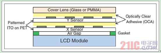
Figure 2. Layer structure of a mutual-capacitive touch screen sensor (not proportional to the real object).
LCD VCOM type: LCD VCOM is the "common mode voltage", which is the reference voltage of the LCD screen. AC VCOM or DC VCOM may be used depending on system requirements. AC VCOM is alternating, while DC VCOM is constant voltage. The former method produces more noise.
Air gap between touch screen sensor and protective lens: One of the most common problems reported by touch device users is the protection lens breakage. To make the product thinner, the capacitive touch screen sensor can be pressed to the back of the protective lens, but when replacing a broken protective lens, the touch screen sensor must also be replaced, which increases maintenance costs. To avoid this cost, as well as the cost of the low yield of the press-fit process, a pad is typically used to separate the touch screen sensor from the protective lens.
Nevertheless, when an air gap occurs between the touch screen sensor and the protective lens, the touch screen sensor may have difficulty detecting the finger touch behavior because the air dielectric constant is low and the strength of the signal generated by the finger touch is low. One way to solve this problem is to increase the sensitivity threshold of the touch system, but this can be dangerous because the sensor will receive some spurious signals, such as LCD or other environmental noise, making it difficult for the touch screen sensor to distinguish the touch action from the noise. .
Industrial design requirements: Some device manufacturers have made touch screen sensors directly on the display to make the overall design thinner. But this is also risky because the touch screen sensor is placed directly on the noise source. One solution is to add a shield between the touch screen sensor and the display. However, adding more than one layer of ITO will increase the overall material cost and have an effect on light transmission.
Integrated touch screen sensor: In order to reduce production costs, LCD manufacturers began to make touch screen sensors directly on the color filters under the polarizer. This method does not require external sensors and compression, but the touch screen sensor is closer to the display, further increasing the noise received by the sensor.
Touch screen controller position: Capacitive touch screen controllers are usually located on the touch screen cable (the chip is on the wire or PCB) and sometimes placed directly on the touch screen sensor (the chip is on the glass). However, for ease of testing, some designs require the touch screen controller to be placed on the system board. This may require a very long flexible circuit board (FPC) to connect the touch screen sensor to the controller. The long FPC acts as an antenna and easily absorbs noise, making it difficult for the touch screen controller to handle weak signals from the touch screen sensor.
Other noise sources: The main noise sources for mobile devices are LCD screens, LCD inverters, WiFi antennas, GSM antennas, and various high-speed circuits in devices. Ambient noise also has a large impact on the touch system. For example, some AC power sources generate strong noise, which will propagate through the AC adapter. Similarly, when the device is placed near a strong noise source such as a desktop fluorescent lamp, the touch system mistakes the noise for an effective touch behavior.
Under normal conditions, for normal-sized fingers (>7mm), high-SNR controllers do not have a significant advantage over low-SNR controllers, only in strong noise environments, such as using a writing pen or wearing gloves. Finger input, the advantage will be reflected when the signal is weak. Low SNR controllers cannot distinguish signals from noise. If the sensor threshold is lowered to increase the detection sensitivity, the touch system can be easily triggered by mistakes, causing misoperation, which is absolutely not allowed in practical applications.
Application Challenges Touch Accuracy: Touch accuracy is an important indicator of touch screen sensor design. For example, in virtual keyboard applications, characters are compactly placed in a small area, accurately responding to touch actions, and avoiding false input of characters is critical. One way to improve accuracy is to add more sensor channels to the controller to support higher touch screen sensor grid densities. But this will come at a cost, because both touch screen sensors and touch screen controllers require more pins. In addition, more sensor channels require more traces at the touch screen boundary, which increases the border width.
The high SNR touch screen controller enhances detection accuracy because it provides better detection of weak signals and collects sampled data from a larger perimeter, while a larger detection range provides more reference points for touch locations. Can be accurately calculated. Figure 3 reveals the effect of the touch screen controller SNR on the accuracy of the scribe line, which is a straight line drawn by a robotic arm holding a 4mm piece of metal. The line drawn by the high SNR controller is clearly smoother than the line drawn by the low SNR controller. Note that these measurements are recorded by the same touch screen sensor and the same post-processing software to ensure a fair comparison. 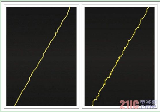
Figure 3. A straight line drawn by a robotic arm holding a 4mm piece of metal. The left side uses a high SNR touch screen controller; the right side uses a low SNR touch screen controller.
Writing pens: Resistive touch screen users have long been accustomed to using pointed pens. Typical resistive touch screen writing pen tip diameter is less than 1mm, usually made of non-conductive plastic. For capacitive touch systems, detecting such a small, non-conductive device is difficult because it provides a very weak signal to the touch screen controller. The tip of the pen used in many touch systems on the market is large (3-9mm), making writing and painting difficult, because the thick tip makes the writing traces blurred.
As long as the pen is wrapped with a conductive material (a relatively small sacrifice), a high SNR touch screen controller can detect a pen with a 1 mm diameter nib. Figure 4 illustrates the effect of the touch screen controller SNR on the pen test results of a 2 mm conductive tip. It is difficult for a controller with low SNR to recognize a small pen tip from the background noise, especially in the portion where the screen noise is the largest. A pen with a 1 mm pen tip at low SNR will cause the useful signal to be drowned in the background noise, rendering the pen unusable.
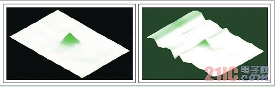
Figure 4. A cross-sectional view of the capacitance of a 2mm conductive pen on a 4-inch screen with a high-SNR touchscreen controller on the left and a low-SNR touchscreen controller on the right. The pen is on top of the green cone; the height of the white plane represents background noise. The increase in signal-to-noise ratio effectively reduces the background noise amplitude, as shown on the left. If the pen in the picture on the right moves to the left of the screen, the signal will be overwhelmed by the noise and the pen will not work.
Non-contact detection: Proximity detection is gradually being adopted in touch screen applications. For example, by increasing the sensitivity of the touch system, when using an e-book, the user can gesture to turn pages without actually touching the screen. However, the sensitivity of touch systems is also easily triggered by ambient noise. Designers have been trying to find the best balance, both to maximize the proximity and not to cause false triggers. Mitsubishi has done some interesting research in this area. They built a touch system that automatically adjusts sensitivity based on whether the touch finger is floating or a real touch. 2
Glove operation: In medical applications, the touch screen needs to be able to work with surgical gloves. Similarly, car touch screen GPS needs to be used when wearing gloves in winter. Most gloves are made of dielectric materials, which makes it difficult for touch screen sensors to detect touch movements. Increasing the sensitivity of the touch screen controller may cause false triggering when the user does not wear gloves. The only solution is to require the application (or user) to choose different sensitivities depending on the situation.
Conclusion The high SNR capacitive touch screen controller offers many advantages for a wide range of design and application requirements such as writing pens, small fingers and gloves. It can help improve touch accuracy without the need for specialized ITO sensor styles or increased sensor channels. It meets the requirements of a variety of displays and different backlights while maintaining good touch performance, providing a more flexible choice for sensor design and production. The touch system can work in a noisy environment and reduce the noise of the device itself from LCD, WiFi antenna, GPS antenna and AC adapter. It gives equipment OEMs more freedom to choose components. Finally, from a performance point of view, it provides precise touch accuracy. In summary, high SNR touch screen controllers can help end users achieve more reliable applications.
Sensor Trash Can,Foot Sensor Automatic Dustbin,Foot Sensor Dustbin,Foot Sensor Trash Can
NINGBO ZIXING ELECTRONIC CO.,LTD. , https://www.zixingautobin.com