Abstract: In order to analyze the interference effect of electromagnetic waves emitted by automobiles on 2.4 GHz wireless communication, several kinds of radiated electromagnetic interference sources of automobiles are discussed, and the spectrum analyzer is used to measure the radiated electromagnetic of two vehicles in the 2.4 GHz frequency band. The relative intensity of the interference, the measurement results show that the electromagnetic interference intensity of the car in the 2.4 GHz band is very small, it can be inferred that the car has little effect on the 2.4 GHz wireless communication.
Keywords: automobile; electromagnetic interference; wireless communication; interference intensity
0 Introduction Electronic and intelligent has become the main direction of automotive technology development. Hyundai vehicles carry a large number of electronic devices, such as high-performance microprocessors, electronic transmissions, automatic cruise controllers, electronic fuel injection systems, in-vehicle communication entertainment and navigation systems. These electronic devices emit high-frequency electromagnetic waves into the space during operation, which in turn interfere with the normal operation of other circuits to form so-called electromagnetic interference. Electromagnetic interference generated by automobiles will not only affect the normal operation of other electronic devices, but also affect the normal operation of the automotive electrical system itself.
The ISM is an industrial, scientific, and medical frequency band. The International Telecommunications Union's Wireless Communications Committee stipulates that this band can be used free of charge as long as the transmitting power of the device is below a certain value and does not cause interference to other frequency bands. The most commonly used ISM bands in the world are 433 MHz, 915 MHz and 2.4 GHz. Among them, 2.4 GHz is the common ISM band of all countries. Currently, wireless devices such as wireless LAN, Bluetooth, ZigBee, and WirelessUSB operate in the 2.4 GHz band.
The problem of electromagnetic interference has been around for a long time. Since 1906, people have proposed to limit the electromagnetic interference generated by automobiles. As the main source of electromagnetic interference, the ignition system has become the focus of research. The main purpose of this experiment is to infer the interference effect on the 2.4 GHz wireless communication equipment deployed in the vehicle by analyzing the relative intensity of the electromagnetic interference source generated in the vehicle and the measured vehicle in the 2.4 GHz band. .
1 Electromagnetic interference source of a car Electromagnetic interference is generated by an interference source, which is an electromagnetic phenomenon that is external and detrimental to a useful signal. There are two types of interference between cars and on-board electrical equipment. The first type is radiated interference. Electromagnetic waves directly penetrate into the electronic device through free space, and excite the internal circuit of the device to generate corresponding interference energy on the circuit, causing logic errors in the circuit, and strong electromagnetic interference can even be directly damaged. Sensitive electronic devices; the second type is conducted interference. The interference source couples the interference signals to other devices through cables such as power lines and signal lines, which is harmful to the normal operation of other devices. For the independently powered vehicle 2.4 GHz communication equipment, it is mainly subject to the radiated electromagnetic interference of the automobile, so this paper mainly analyzes and measures the radiated electromagnetic source of the automobile.
According to the theory of electromagnetic wave generation and propagation, as long as the electromagnetic oscillation is caused on the linear circuit, alternating equal-numbered electric charges are generated at both ends of the linear circuit, and such a circuit emits electromagnetic waves into the space. The energy radiated by electromagnetic waves per unit time is proportional to the fourth power of the frequency, that is, the higher the oscillation frequency of the circuit, the easier it is to radiate electromagnetic waves. There are many circuits in the car that meet this condition, so the car can emit electromagnetic interference at various frequencies. For every doubling of traffic density, the spectral density of interfering noise power is increased by 3 to 6 dB(A).
The strongest source of electromagnetic interference in automotive electrical systems is the ignition system. When the car engine is running normally, the transient voltage of the ignition coil secondary is high and can rise to 35 kV within 50μs. When the spark plug electrode is discharged, strong electromagnetic radiation is formed to propagate to the surrounding free space. This radiated electromagnetic noise contains a high frequency component and is the main source of interference for television broadcasting.
There are many inductive loads on the car, such as various motors and solenoid valves. The coil of the solenoid valve produces a reverse voltage that is several tens of times its operating voltage at the moment of opening. This reverse voltage continues to resonate in an LC series oscillating circuit formed by the inductor and the distributed capacitance, producing electromagnetic radiation that is very rich in harmonics. This is also a very important source of electromagnetic interference.
There are also many contact switches on the car. Due to the contact resistance of the contacts, the switches often generate sparks when they are opened and closed. If the current in the circuit is relatively large, the electromagnetic radiation caused by the spark can also interfere with other electrical equipment. When the DC motor is working, the carbon brush and the commutator also generate strong sparks, causing radiated electromagnetic interference in a wide frequency range. The wiper motor of a car generally uses a DC motor, and the external interference is also strong.
2 Measurement and analysis of radiated electromagnetic interference in automobiles
2.1 Measurement method In the 2.4 GHz frequency band, the electromagnetic wave power of the environment in which the vehicle is located and the electromagnetic wave power when the vehicle is operating in the same environment are separately measured. By comparing these two values, the relative intensity of electromagnetic interference generated by the car in the 2.4 GHz band can be obtained.
2.2 Measurement process The measurement process is as follows:
(1) Install the spectrum analyzer. The spectrum analyzer has a logging software and drivers that run on the Windows operating system. First start the laptop, connect the spectrum analyzer FR24-SAU to the laptop with the USB cable, install the driver of the spectrum analyzer after the operating system prompts to find new hardware, and finally install the recording software FRMT of the spectrum analyzer on the laptop. .
(2) Measuring environmental noise. Place the antenna of the spectrum analyzer in the co-pilot position, start the laptop and run the recording software of the spectrum analyzer, set the parameters of the spectrum analyzer on the recording software, turn on the peak hold function of the spectrum analyzer, and turn off the car. The engine and all on-board electrical equipment were continuously measured for 3 min and the measurement results were recorded as “environmental noiseâ€.
(3) Measuring car noise. Similar to the procedure for measuring ambient noise, turn on the peak hold function of the spectrum analyzer. During the measurement period, the engine of the car was kept in operation. During the period of 30 s, the throttle and switch turn signals were added once every 3 seconds, and the result was recorded as “car noiseâ€.
In order to obtain a relatively stable measurement environment and reduce the influence of other interference sources on the measurement results, the measurement time is selected at 11:00 pm, and the measurement location is selected at an open space of more than 200 m from the residential building. The WiFi wireless network function that comes with the notebook must also be turned off during the measurement to prevent it from affecting the measurement results.
2.3 Measurement results The spectrum analyzer FR24-SAU has a total of 256 measurement points in the 2.4 GHz band with a measurement interval of 330 kHz.
Figure 1 is a noise power diagram of the environment in which the Bell RJ B6950VCBED truck is located. Figure 2 is a graph showing the noise power measured during operation of the Bell RJ B6950VCBED truck. Figure 3 is a noise power diagram of the environment where the Golden Brigade XML6483 van is located. Figure 4 is a graph of noise power measured during the operation of the Golden Brigade XML6483 van. The white curve in the figure is the cumulative peak of the power measured continuously for 3 min.
This article refers to the address: http://
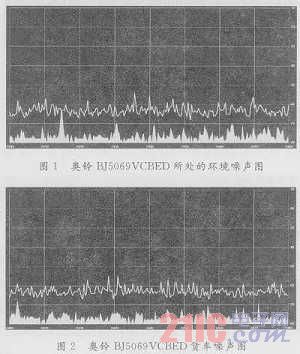
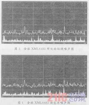
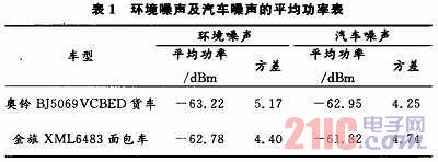
Table 1 shows the average ambient noise power and average car noise of the Austrian Bell BJ5069VCBED truck and the Golden Travel XML6483 van.
2.4 Analysis of measurement results The radio channel is the transmission path between the transmitter and the target receiver. It has random and time-varying characteristics, so it is difficult to establish a model. The electromagnetic wave propagating in free space, the power at the receiving point is determined by the Friis free space equation: ![]()
Where: PR(d) is the received power; PT is the transmit power; GT is the transmitter antenna gain; GR is the receiver antenna gain; d is the distance between the transmitter and the receiver, the unit is m; λ is the wavelength of the electromagnetic wave, Unit: m.
The path loss is equal to the ratio of the transmitted power to the received power. The path loss equation derived from equation (1) is: ![]()
Where: PL is the path loss in dB.
Let both the transmit and receive antennas be unity gain, the frequency of the electromagnetic wave is 2.4 GHz, and the equation for the relationship between path loss and transmission distance is: ![]()
From the measurement results in Table 1, it can be seen that the "car noise average power" is 0.27 dB and 0.96 dB larger than the "ambient noise average power" in the 2.4 GHz band. For 2.4 GHz wireless communication equipment, electromagnetic interference from automotive electronics increased the path loss by 0.27 dB and 0.96 dB.
The transceivers are all in accordance with the preconditions of equation (3). The output power of the transmitter is PT=6 dBm, the ambient noise is -63 dBm, the signal-to-noise ratio is 4 dB, and the received power is PR=-63+4=-59 dBm. The path loss of communication PL1=PR-PT=6-(-59)=65 dB, and the communication distance d1=18.6m is obtained according to equation (3). If the added path loss of the vehicle electromagnetic interference to the wireless communication device is 0.96 dB, the actual available path loss is reduced by PL2=PL1-0.96=64.04 dB, and the corresponding transmission distance is obtained according to equation (3). D2 = 16.7 m. This shows that after the car works, to achieve the same communication quality, the communication distance of the wireless device will be shortened by d1-d2=1.9 m.
3 Conclusion Observing the measurement results, the electromagnetic interference generated by the car in the 2.4 GHz band is small. Through analysis and calculation, it can be inferred that ordinary car-mounted electrical equipment will not cause destructive interference to the normal operation of 2.4 GHz wireless communication equipment. Of course, only the actual communication quality test in the car can get the exact impact of the car on 2.4 GHz wireless communication.
Our factory provides 4.3",5", 7" ,9" wired and wireless rear view mirror monitors.Really help you see the image behind your vehicle when you are reversing.
4.3/5/7/9/10.1 inch monitor has a pixel resolution of 800 x 480 /1024*600 and displayed is a sharp clear digital image. Monitor has 2 Channel Video Input; V1/V2 optional. PAL&NTSC for choose. Monitor automatically turns on and switch to rear view camera when reversing.
7-Inch TFT LCD screen Monitor with Built-in Wireless Receiver-- High resolution image and full color display.
Digital Color Rearview Monitor
Rear View Monitor,Digital Color Rearview Monitor,Backup Mirror Monitor,Backup Monitor For Trucks
Shenzhen Sunveytech Co.,LTD , https://www.sunveytech.com