Abstract: In recent years, the logistics industry has developed rapidly. A design scheme of logistics vehicle monitoring terminal based on GPS (Global Positioning System) and CDMA (Code Division Multiple Access) technology is proposed. The S3C2440 A ARM chip is used as the main control chip, and the appropriate GPS module and CDMA module are selected for hardware design. The study analyzed GPS and CDMA technologies. The GPS serial port receiving program and the wireless communication program between the terminal and the monitoring center are designed on the WinCE 5.0 platform. The results show that the system runs stably, the data refresh time is less than 3 s, and the GPS position drift value is less than 20 m.
Keywords: global positioning system; code division multiple access; WinCE 5.0; embedded operating system; logistics terminal
With the continuous development of China's national economy and transportation industry, the logistics and transportation industry has become an indispensable basic industry to promote the rapid development of the national economy. Although various types of logistics and transportation warehousing companies have accumulated rich practical experience in the long-term development process, real-time monitoring of vehicle dynamic information has not been solved satisfactorily. For example, information feedback is not timely, inaccurate, and incomplete. A lot of waste of transportation capacity and operating costs remain high. The use of GPS to manage and monitor logistics vehicles and logistics objects has become a development trend.
In view of the above situation, this paper studies the logistics vehicle monitoring terminal and proposes the overall system architecture based on GPS+GIS+CDMA. The system integrates Global Position-ing System (GPS), Geographic Information System (GIS), and CDMA (Code Division Multiple Access) wireless communication technologies.
The logistics transport vehicle monitoring terminal designed in this paper obtains the latitude and longitude information of the vehicle through GPS satellite positioning, communicates with the monitoring center through the CDMA wireless communication network, and transmits various information of the transport vehicle to the monitoring center in real time for the monitoring center. The overall transportation fleet is displayed, inquired and dispatched.
1 System overall design The logistics and transportation vehicle monitoring system based on GPS and CDMA consists of vehicle monitoring terminal, data transmission network and monitoring center. The data transmission network consists of a CDMA network and the Internet.
Through the GPS satellite network, the vehicle terminal can accurately locate the logistics vehicles and logistics objects, connect to the monitoring center server via the CDMA wireless network, and transmit the latitude, longitude, speed, heading, altitude, time and other GPS of the logistics vehicle to the monitoring center in real time. Data information, the monitoring center can display and query various information of the vehicle on the electronic map with geographic information processing and query function, and monitor the running state of the vehicle in real time.
In addition, the monitoring center also has the function of communicating with the vehicle-mounted terminal, which can timely dispatch the logistics and transportation vehicles and timely deal with sudden accidents, and is applicable to various logistics and transportation fields.
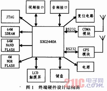
2 Terminal hardware design The hardware structure of the logistics vehicle terminal designed in this paper consists of S3C2440A, JTAG on-chip debugging interface, video interface, audio interface, reset circuit, CDMA wireless communication module, GPS module, Power Supply circuit, LCD touch screen, keyboard, etc., external SDRAM, NAND FLASH, NOR FLASH as an external memory, its hardware structure is shown in Figure 1.
This article refers to the address: http://
2.1 CPU selection In order to meet the requirements of the system for real-time, large data processing, GPS signal reception, CDMA data transmission, etc., the terminal uses Samsung's S3C2440A 32-bit ARM chip as the CPU. S3C2440A adopts advanced ARM920T core, on-chip integrated 3 UART serial port, 2 SPI ports, 8 10-bit ADCs, RTC with calendar function, on-chip clock generator with PLL, 130 general I/O ports, 24 A rich source of external interrupt sources, easy to develop, is a very cost-effective chip.
2.2 CDMA module interface design The terminal uses Huawei EM200 CDMA1X module. The module operates at 800 MHz, with a maximum transmit power of 0.25 W, a receiver sensitivity of less than -106 dBm, and an operating voltage of 3.3 to 4.2 V. It integrates a rich resource interface such as UART, UIM card, and antenna. Support for standard AT instruction sets. The limit working temperature is -30 °C ~ +75 °C, and the working temperature range is wide, suitable for various logistics and transportation environments.
The S3C2440A has three UART serial ports. The EM200 module is connected to the S3C2440A through the serial port 1. Because both inputs and outputs are TTL levels, they can be directly connected without level shifting, among which EM200 ![]() The pin is the data output end, connected to the RXD end of the S3C2440A; EM200
The pin is the data output end, connected to the RXD end of the S3C2440A; EM200 ![]() The pin is the data receiving end and is connected to the TXD end of the S3C2440A, thereby realizing data transmission and reception between the two. The connection diagram of Huawei EM200 CDMA1X module and S3C2440A is shown in Figure 2.
The pin is the data receiving end and is connected to the TXD end of the S3C2440A, thereby realizing data transmission and reception between the two. The connection diagram of Huawei EM200 CDMA1X module and S3C2440A is shown in Figure 2.
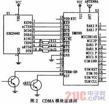
The TX3, nRTS0, and DTR pins of S3C2440 pass through three 1 kΩ resistors and EM200 respectively. ![]() The feet are connected to prevent damage to the chip caused by excessive current.
The feet are connected to prevent damage to the chip caused by excessive current.
2.3 GPS module interface design GPS module is the key to achieve accurate positioning of the terminal, is the core of the terminal design, so the terminal selects the GFE company's SIFEIII generation GS-15B module.
The GS-15B is a high-performance, low-power smart satellite receiver module. It adopts the MT3329F satellite positioning receiver chip designed by Taiwan Lianfa Technology Co., Ltd. It is a complete satellite positioning receiver. At the same time, it has all-round functions to meet the strict requirements of professional positioning and industrial-level requirements. Built-in GPS antenna, MTK 329F with MTK high sensitivity and low power consumption. Ability to quickly locate and track 32 satellites. Ultra-small size, the chip has built-in 200,000 satellite tracking operators, which greatly improves the ability to search and calculate satellite signals. Support NMEA-0183 v2.2 version specification output. Receive sensitivity is -157 dBm, operating temperature is -40 °C ~ 85 °C, TTL level output, working voltage 3.3 ~ 5.0 V, cold start positioning time is only 42 s, average positioning accuracy is 10 ~ 15 m . It not only satisfies the demand for cost-effectiveness of the terminal, but also satisfies the precise positioning of the terminal.
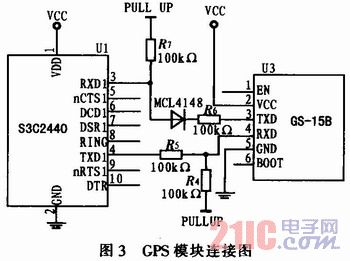
The interface connection diagram between S3C2440A and GS-15B is shown in Figure 3. The terminal uses the serial port 2 of the S3C2440A to connect the GPS module. In order to enhance the driving capability, two 100 kΩ pull-up resistors are added to the TX3 and PXD1 pins of the S3C2440A. The terminal generally only receives GPS information and does not write to the GPS. Therefore, in order to protect the chip, a 100 Ω resistor and a reverse diode of the MCIA148 are added between the RXD1 and GS-15B of the S3C2440A, thus ensuring The terminal is stable when it is running.
3 Terminal software design The software part of the terminal is designed based on WinCE 5.0 embedded operating system. WinCE is a multi-tasking, fully preemptive 32-bit embedded operating system, supporting WinCE MFC, ATL, WinCE API and some additional Programming interface and various communication technologies. The WinCE embedded operating system has the advantages of good operation interface, high real-time performance, low resource consumption, rich development tools and strong technical support, which fully meets the design requirements of the terminal software.
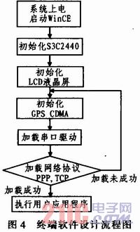
3.1 Terminal software design flow First, the system is powered on, boot bootloader, load WinCE kernel, start WinCE embedded operating system. Then initialize the peripheral modules such as CPU, LCD, GPS, CDMA, and then load the serial port driver and network protocol. If the loading is successful, execute the user application. If the loading fails, return, reload the serial port driver and network protocol. The user application of the terminal includes: a CDMA wireless network access program, a network data transmission program, a GPS serial port receiving program, and the like. The terminal software design flow chart is shown in Figure 4.
3.2 CDMA wireless network access procedure The terminal controls the CDMA module through AT commands to realize wireless network access and network data transmission.
After the system is running, first initialize the CDMA module, set the baud rate to 115 200 b/s, and then enter the dial-up waiting state. The terminal logs in to the network through the PPP dial-up connection. The access number is 777, and the username and password are both cards. After confirming that the login network is successful, the GPS serial port receiving program and the network data transmission program are called, and the GPS positioning information of the terminal is sent to the monitoring center in a timed manner.
The AT command and the return value of the PPP (point-to-point protocol) connection are as follows: 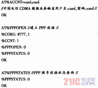
3.3 CDMA wireless network communication program After the terminal accesses the Internet through the CDMA network, the wireless network communication program uploads the GPS data analyzed by the terminal to the monitoring center through the Internet. The terminal software is designed to use the stream format socket for network communication, corresponding to the connection-oriented TCP protocol in the TCP/IP protocol. The network data transfer program is programmed with a client/server mechanism, and the terminal (client) process is manipulated by the user; the monitoring center (server) process resides on the host continuously, waiting for the terminal connection request to enter.
The network communication program flow of the monitoring center is as follows: 1) Create a socket with the socket() function and assign a value to the socket address structure; 2) Bind the socket to the local IP address and port number with the bind() function, select static IP address; 3) use the listen() function to listen for connection requests on the socket; 4) use the accept() function to receive the terminal connection request, generate a new socket and description word and connect to the terminal, using the new socket Send and receive data; 5) Use the fork() function to derive a new child process to communicate with the terminal, and the parent process continues to listen for other requests. In this way, the problem that the monitoring center can no longer communicate with other terminals after establishing a connection between the terminal and the monitoring center can be avoided.
The TCP program flow of the terminal is as follows: 1) Create a local socket with socket(), assign a value to the address structure of the monitoring center socket; 2) Use the connect() function to make the local socket interface actively send a connection request to the monitoring center socket. Three-way handshake to establish a TCP connection; 3) If the connection is established successfully, use the send() and recv() functions to communicate with the monitoring center; 4) End the communication, close the socket with close().
3.4 Terminal GPS Serial Port Program Software development tools use EVC (embedded visual C++). EVC is the mainstream development tool on Windows CE, which encapsulates the underlying network communication, COM interoperability, and RAPI. EVC supports a subset of the MFC class library, so that VC programs on the Win32 platform can be easily ported to the WinCE platform.
The terminal GPS serial port program mainly performs two functions: receiving GPS data and parsing GPS data. The GPS module output follows the NMEA-0183 standard. The program flow is as follows:
1) Open the serial port by using the OpenPort() function. This function uses the create file function CreatFile() to open the serial port 2 to obtain the operation handle m_hComm of the serial port 2;
2) If the serial port 2 is successfully opened, the current serial port setting is read, that is, the serial parameter structure DCB variable is read by GetCommState();
3) Use SetCommState() to set the serial port 2 accordingly: if the baud rate is set to 4 800 b/s, 8 data bits, no parity, 1 stop bit, no data flow control;
4) Read the data bit by bit to determine whether the frame start is $GPRMC. If it is $GPRMC, extract the time, longitude, latitude, speed and other information from it and store it in the corresponding structure; determine whether the frame start is $GPGGA, if For $GPGGA, extract the altitude from the 9th field and store it in the corresponding structure; determine whether the frame start is $GPGSV, and if it is $GPGSV, extract the effective satellite number, effective satellite number and other information from it and store it in the corresponding structure;
5) Display the received GPS data and the parsed GPS information on the LCD using SetWindowText();
6) Finally, close the serial port 2 with the ClosePort() function when needed. This function closes the handle of the serial port 2 m_hComm using CloseHandh().
4 Operation results The terminal software running results designed in this paper are shown in Figure 5. The terminal GPS data display includes UTC time, latitude and longitude, ephemeris, direction, altitude, and the like. It realizes the function of displaying GPS data comprehensively and intuitively, and has a friendly human-machine interface style. In Figure 5(a), the GPS serial port can be configured and the original NEMA-0183 statement received is displayed. The latitude and longitude in Figure 5(b) is measured in the new campus of Hebei University of Technology in Beichen District, Tianjin, accurate to the second level, the longitude is 117°41'34.4" longitude, and the latitude is 39°37'6.2 north latitude. ". The test time is June 6, 2010, at 16:24 pm and 22 seconds.
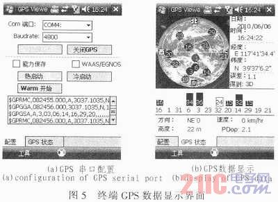
Tests show that the terminal software can run smoothly on the embedded WinCE 5.0 system with good real-time and accuracy.
In addition, the terminal transmits the GPS positioning data to the monitoring center in real time through the CDMA wireless communication network, and the geographic location of the terminal is displayed in real time on the electronic map of the monitoring center. After testing, the actual position of the terminal is completely consistent with the position on the electronic map, and has good real-time performance, the data refresh time is less than 3 s, and the GPS position drift value is less than 20 m.
5 Conclusions In view of the rapid development of China's logistics industry, this paper has designed software and hardware for logistics vehicle monitoring terminals based on GPS and CDMA. Realized remote monitoring and real-time scheduling of logistics vehicles. Compared with the traditional vehicle terminal, this design uses a 32-bit ARM processor, which has the advantages of faster processing speed, larger storage space and more intuitive interface display. Especially in the wireless transmission of GPS data, CDMA wireless communication technology is adopted, which is more suitable for the field of vehicle terminals with long distance, large data volume and high real-time requirements than traditional GPRS technology. With the development of 3G mobile communication systems, GPS terminals using CDMA networks are more likely to smoothly transition to 3G networks, which will have broader application prospects.
ZhenHuan's non-Dimmable Led Driver provides the output power range from 3 Watts to 60 Watts and normal AC input voltage range from 110vac to 240vac. The series led power supplies is IP20 rated and are suitable for indoor installations, offers both UL Listed and UL Recognized style enclosures.
Led Driver 12V,Led Driver,24V Dc Led Driver,Power Supply Transformer
Shenzhenshi Zhenhuan Electronic Co Ltd , http://www.szzhpower.com