The digital clock is a device that uses digital circuit technology to realize time, minute and second timing. The design process of the traditional digital clock has to be proposed in three stages: design proposal, scheme verification and modification. Generally, the method of lapping experimental circuits is used, and it is often necessary to repeat the experiment and modification until the correct conclusion is designed, such as the circuit design of the multi-function digital clock in the reference. With EDA tools, electronic designers can design electronic systems from concepts, algorithms, protocols, etc. A lot of work can be done by computer, and the whole process of electronic products from circuit design and performance analysis to designing IC layout or PCB layout. Automatic processing is done on the computer.
Electronic products can be completed with EDA tools from system design, circuit design to chip design and PCB design. Simulation analysis, rule checking, automatic layout and automatic routing are the most effective parts of computers to replace labor. With EDA tools, design cycles can be significantly reduced, design efficiency can be improved, and design risks can be reduced.
The Protel99SE is a 32-bit printed board aided design package with powerful design features for schematic, printed board design and programmable logic device design.
1 Digital clock works
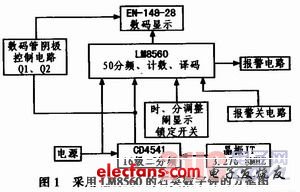
The digital timer is generally composed of an oscillator, a frequency divider, a counter, a decoder, a display, and the like. These are the most widely used circuits in digital circuits, and their block diagrams are shown in Figure 1.
2 counting and decoding LM8560 components
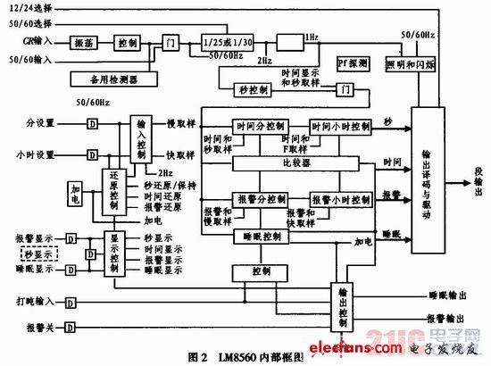
The counting and decoding part uses the LM8560 component. The LM8560 is a PMOS LSI with a dual in-line plastic package and a 4-digit digital display. The equivalent principle block diagram is shown in Figure 2. Features: drive 7-segment LED light tube display; 50/60Hz work; 12/24 hour display; 12 hours display AM (AM), PM (PM) indication; lead zero turn off; 9 minutes snoring alarm; preset 59 minutes ( Or 1 hour 59 minutes) sleep timing; preset alarm within 24 hours; use touch incrementer to set control; power failure indication; standby RC oscillator; 900 Hz tone output.
1) 50/60 Hz output Select the domestic AC power frequency to be 50 Hz, as long as the 26-pin (50/60Hz selection) is connected to Vss. If the power frequency is 60 Hz, this pin is not connected.
2) 12/24 hour display selection The 28th foot (12/24 hour selection) can be connected to Vss to display the 24-hour format; this foot is not connected and can display the 12-hour format.
3) When the CR input is powered off, the backup battery is automatically powered, and the clock oscillator inside the chip works immediately. Instead of 50/60 Hz input, the control time counter continues to count, but it does not display; when it is incoming, it automatically switches to AC power and resumes display. In this way, although the power is cut off, it can still be accurately timed. The values ​​of R and C at the CR input determine the frequency of the on-chip clock oscillator. The standby oscillator has a stability of ±10% and an accuracy of ±10%.
4) The time base of the 50/60 Hz input time counter is input from this terminal (25th pin) when supplied from 50/60 Hz AC power. This terminal is connected to a simple RC filter circuit to eliminate the influence of power supply voltage transients, which may cause clock misinterpretation or device damage.
5) Display mode selection Use the single-pole single-throw switch to select one of four displays: time, second, alarm time, sleep time.
6) Time setting input hour setting and minute setting end are used to align time or set alarm and sleep time. The sleep timer can be set to 1 hour and 59 minutes with the hour setting in the sleep display mode, otherwise it will be set to 59 minutes.
7) Power failure indication If the power is turned off and then called again, all the strokes will flash at 1 Hz, and then the hour setting and minute setting input can be used to restore.
8) Alarm output and alarm off input If the alarm setting matches the real-time time, the output of this terminal controls the external circuit to send a 900 Hz tone at 2 Hz. It can last for 1 hour and 59 minutes unless it is reset by an alarm off input or a snoring input and returns to normal. In addition, a DC output can be obtained by a simple low-pass filter for use as a control signal.
9) During the alarm, this input can temporarily turn off the alarm for 9 minutes, then the alarm signal is reproduced; it can be reused within 1 hour and 59 minutes of the alarm.
10) Sleep timing and input are normally turned on automatically during the 59 minute (or 1 hour 59 minutes) interval, and the radio is automatically turned off after 59 minutes (or 1 hour 59 minutes). The radio can also be manually controlled by tapping the input.
11) Use the plate voltage limit on any foot: +0.3~-15.0 V, working temperature: -20°C~+70°C, storage temperature: -55°C~+150°C, lead wire maximum temperature (welding 10 s): 300 ° C.
Wifi Control Vacuum Cleaner,Thinnest Robot Vacuum Cleaner ,Air Purifier Wifi Control,Low Noise Cleaner Robot
NingBo CaiNiao Intelligent Technology Co., LTD , https://www.intelligentnewbot.com