The following figure shows the novel circuit of the IR53HD420 driving LED. In the figure, VDC is DC 320V. Obtained by rectification and filtering by 220V AC. The IR53HD420 output produces 320Vp-p connected to a series-connected compact fluorescent tube and a current-limiting inductor L1, and connected to a parallel capacitor to form LC resonance for heating. Light up the fluorescent tube. And provide the lamp current. The device works very well. The compact fluorescent tube voltage is typically 150Vp-p. Dozens of LEDs (LEDI-LED64) are connected in series. Connect them to a Bridge Rectifier (D1 - D4). It can mimic the effect of a compact fluorescent lamp, at least in the on state. The values ​​of Rt and Ct given in the figure make the bridge operate at 70 kHz. This circuit supplies approximately 64 mA of current to 64 LEDs. The LED current consists of DC plus a small ripple current. Maintaining low ripple current is beneficial for high efficiency and extended LED life. During one oscillation period, the voltage at the input of the LED rectifier does not change. Therefore, the current on the inductor L1 is a triangular wave. This is good for EMC (electromagnetic compatibility). The average current equation of the LED is Iledaug=(1/2VDC—NxVFled), (4xfxLl), where VDC is the power source and N is the number of LEDs connected in series. Vnm is the forward voltage drop of the LED. f is the oscillation frequency. L1 is the inductance of the current limiting inductor.
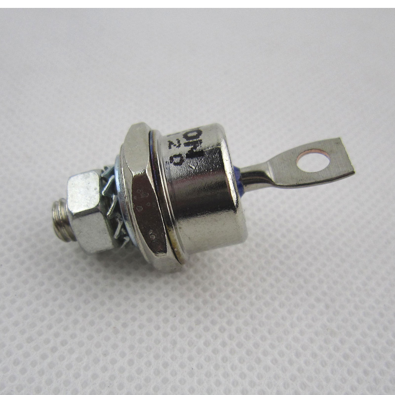
Fast Recovery Diode (FRD) is a semiconductor diode with good switching characteristics and short reverse recovery time. It is mainly used in switching power supplies, PWM pulse width modulators, inverters and other electronic circuits as high-frequency rectifier diodes. Free-wheeling or damper diodes are used. The internal structure of the fast Recovery Diode is different from that of an ordinary PN junction diode. It belongs to a PIN junction diode, that is, a base region I is added between the P-type silicon material and the N-type silicon material to form a PIN silicon wafer. Since the base area is thin and the reverse recovery charge is small, the fast recovery diode has a short reverse recovery time, a low forward voltage drop, and a high reverse breakdown voltage (withstanding voltage).

Fast Recovery Stud Diode,Stud Type Fast Recovery Diode,Fast Recovery Diode,Stud Rectifier Power Diode
YANGZHOU POSITIONING TECH CO., LTD. , https://www.yzpst.com