1. The idea of building a self-made power supply came from trying to calculate the amplifier over the past two days. I noticed that the -12V power supply was too high, which caused the op-amp to malfunction. This led me to think about creating a more stable and adjustable power source for my electronics projects.
2. Schematic
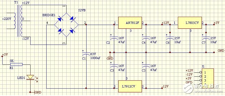
Figure 1, Self-regulation circuit wiring diagram
Description: (1) T1 is a 10W dual 12V transformer purchased from the electronics market for just 9 yuan. Initially, I tried using a small transformer taken from a broken computer power supply, thinking it might work. However, I quickly realized that it had too many pins, making it hard to identify the primary and secondary coils. I attempted to connect only two leads at one end as the primary coil, but when I touched them to 220V, there was a spark and the room went dark. Later, I discovered it was a high-frequency transformer, which works by rectifying and filtering AC before switching it at high frequency. It's small in size but powerful, and this experience taught me to be careful when dealing with such components. Eventually, I bought a proper 10W transformer from the market, which was surprisingly large and reliable! 😊
(2) 7812 and 7912 are common voltage regulators, but their pin configurations can be confusing. After some trial and error, I found a clear diagram that helped me understand the correct connections. If you connect the wrong pins, the output voltages may become unbalanced or even cause issues after the rectifier bridge. Once correctly wired, the voltage regulation performance was excellent.
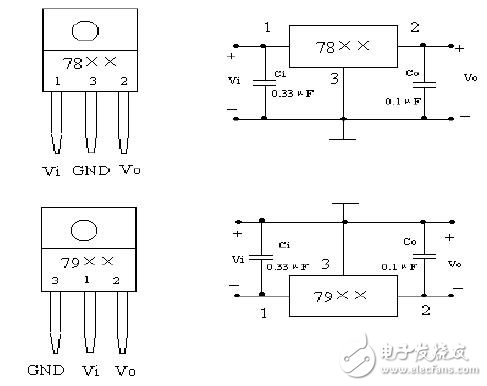
Figure 2, 78xx and 79xx wiring diagram
(3) For the rectifier bridge, I opted to use an integrated module instead of building one from individual diodes. I chose the S2VB20, which can handle 200V DC and 2A of current. Given that my transformer outputs only 10W, this component is more than sufficient for the job.
(4) When it comes to filter capacitors, it seems simple, but there are some important details to consider. Some people suggest using capacitors ranging from hundreds to thousands of microfarads, but it's crucial to pay attention to the voltage rating to avoid breakdown. Also, make sure not to reverse the polarity—connect the positive terminal to 0V and the negative terminal to -12V. I made a mistake once by reversing the capacitor, and it exploded with smoke. The filtering effect was impressive, especially under no load. Using an oscilloscope, I could see how the waveform of the negative half-cycle was smoothed out after adding the capacitor. It became a straight line instantly, proving its effectiveness.
(5) Regarding the 78xx and 79xx voltage regulators, I added capacitors between pins 1 and 2 and ground. This helps prevent high-frequency oscillation and suppresses interference. The capacitor values were chosen somewhat randomly, so don’t take this as a strict guideline.
3. Results
After debugging, the power supply successfully provided three output voltages: +11.80V, -12.11V, and +5.02V, totaling 10W. Unfortunately, I forgot to include a fuse, so I recommend being cautious when using it to avoid damaging the components. It worked perfectly for testing the op-amp. Figure 3 shows a real photo of the setup. Since the little girl wasn’t at school and the camera wasn’t available, I had to use my phone to capture it. 😄
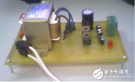
Figure 3, Homemade power supply photo
Dedicated TV cabinet,Smart TV cabinet,Laser intelligent TV cabinet,Laser TV dedicated TV cabinet
Jiangsu D-Bees Smart Home Co., Ltd. , https://www.cI-hometheater.com