1. The idea of building a self-made power supply came from trying to calculate the amplifier over the past two days. I noticed that the -12V power supply was too high, which caused the op-amp to malfunction. This realization led me to explore a more stable and adjustable power solution.
2. Schematic
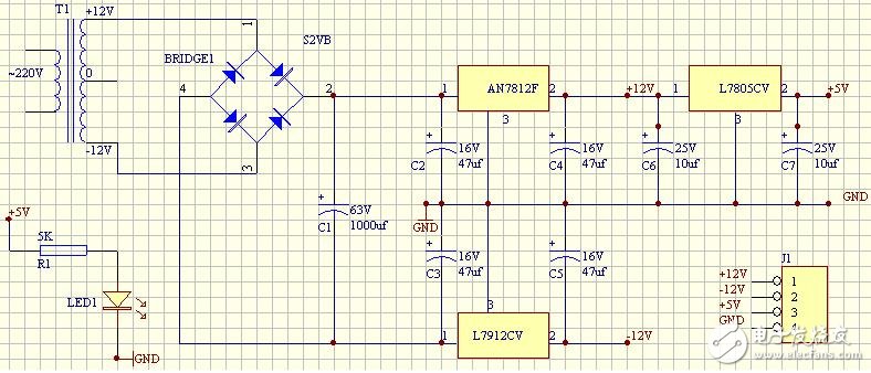
Figure 1, Self-regulation circuit wiring diagram
Description: (1) T1 is a 10W dual 12V transformer bought from the electronics market for just 9 yuan. Initially, I tried using a small transformer from a broken computer power supply, thinking it could be used. However, I quickly realized it had too many pins, making it hard to identify the primary and secondary coils. I took a risky approach by connecting only two leads at one end to 220V, but as soon as I touched it, the room sparked when I disconnected it. Later, I understood it was a high-frequency transformer. These transformers are commonly used in switch-mode power supplies, where they convert AC to DC through rectification and filtering. Their compact size and high efficiency were surprising for a beginner like me. It was a wake-up call to be careful with such components. Eventually, I purchased a proper 10W transformer from the market, and it turned out to be much larger than expected! 😊
(2) The 7812 and 7912 regulators are common parts, but their pin configurations can be confusing. After some research, I found a clear diagram that helped me connect them correctly. If you connect the wrong pins, the output voltage may become unbalanced or even cause issues after the rectifier bridge. Once wired properly, the voltage regulation works very well.
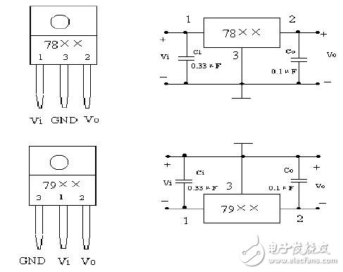
Figure 2, 78xx and 79xx wiring diagram
(3) The rectifier bridge can be purchased as an integrated unit. I chose the S2VB20, which can handle 200V DC and 2A of current. Considering my transformer is only 10W and outputs less than 1A, this component is more than sufficient for my needs.
(4) Filter capacitors seem simple, but there are some important details to consider. Some people suggest using capacitors ranging from hundreds to thousands of microfarads, but it's crucial to pay attention to the voltage rating to avoid breakdowns. Also, make sure not to reverse the polarity—connect the positive side to 0V and the negative side to -12V. I mistakenly reversed one and saw smoke coming out of it. The filtering effect is excellent with no load, and if you look at it with an oscilloscope, you can clearly see the difference. Before adding the capacitor, the waveform after the rectifier bridge looked jagged, but once the capacitor was added, it smoothed into a straight line.
(5) For the 78xx and 79xx regulators, it's recommended to place capacitors between pins 1, 2, and ground to prevent high-frequency oscillation and suppress input interference. I selected the capacitor sizes randomly, so don't take this as a standard reference.
3. Results
After debugging, the power supply successfully outputs DC 11.80V, DC -12.11V, and DC +5.02V. The total output power is 10W. Unfortunately, I didn’t include a fuse, so it’s important to use caution when operating it. I’ve been using it to power the op-amp, and it has worked quite well. Figure 3 shows a photo of the actual setup. Since the little girl wasn’t at school and the camera wasn’t available, I had to use my phone to take the picture. 😄
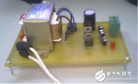
Figure 3, Homemade power supply photo
Three installation methods: ceiling installation, wall mounted installation, and ceiling mounted installation.
Universal Projector Mount,Universal Projector Ceiling Mount,Overhead Projector Mount,Large Projector Mount
Jiangsu D-Bees Smart Home Co., Ltd. , https://www.cI-hometheater.com