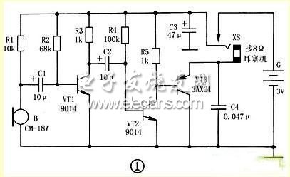
The circuit of the hearing aid is shown in the figure, which is essentially a multi-stage audio amplifier composed of transistors VT1 ~ VT3. VT1 and peripheral RC components form a typical RC coupling amplifier circuit, which acts as front-end audio voltage amplification; VT2 and VT3 form a two-stage direct-coupled power amplifier circuit, in which: VT3 is connected to the emitter output form, and its output The impedance is low to match the 8Ω low resistance earbuds.
This article refers to the address: http://
  
Â
After receiving the acoustic signal, the electret microphone B outputs a corresponding weak electrical signal. The signal is coupled to the base of VT1 via capacitor C1 for amplification. The amplified signal is output by its collector, coupled to VT2 via C2 for second stage amplification, and finally the signal is output by the VT3 emitter and sent through jack XS. Play the sound to the earphones.
In the circuit, C4 is a bypass capacitor, its main function is to bypass the various harmonic components forming noise in the output signal to improve the sound quality of the earphone. C3 is a filter capacitor, which is mainly used to reduce the AC internal resistance of the battery G (actually providing a good path for the audio current of the whole machine), which can effectively prevent the self-oscillation generated by the circuit when the battery is quickly discarded, and the sound of the earphone More clear and loud.
Component selection
VT1, VT2 select 9014 or 3DG8 type silicon NPN low power, low noise triode, require current amplification factor β≥100; VT3 should choose 3AX31 type 锗PNP low power triode, the penetration current Iceo is required to be as small as possible, β≥30 Just fine.
B selects CM-18W type (φ10mm×6.5mm) high sensitivity electret microphone, its sensitivity is divided into five gears, which are represented by color points: red is -66dB, small yellow is -62dB, rhubarb is -58dB, The blue color is -54dB and the white color is >-52dB. White point products should be used in this production to obtain higher sensitivity. B can also be directly replaced with a blue point, high sensitivity CRZ2-113F electret microphone.
XS selects the two-core jack commonly used in CKX2-3.5 type (φ3.5mm caliber) earphones, which can be used after being purchased. For the modification method, as shown in Fig. 2, the inner reed piece clamped by the tweezers is slightly bent downward, and the inner and outer reeds are changed from the original normally closed state to the normally open state. After the plug is inserted, the inner and outer reeds can be reliably connected, and the plug can be reliably separated after being pulled out, so that it can also be used as a power switch. The headset uses an 8Ω low-impedance earphone with a CSX2-3.5 (φ3.5mm) two-pin plug.
R1 to R5 use RTX-1/8W type carbon film resistors. C11 to C3 use CD11-10V type electrolytic capacitors, and C4 uses CT1 type ceramic dielectric capacitors. G is made up of two series of No. 5 dry batteries in series with a voltage of 3V.
The Dc Source System is a single output programmable DC Power Supply which provides with high power density and stable DC output. With built-in voltage and current testing capability, DC Source System can fulfill different kinds of Dc Switching Power Supply applications.
Some features as below:
- With accurate voltage and current measurement capability.
- Coded Knob, multifunctional keyboard.
- Standard RS232/RS485/USB/LAN communication interfaces, GPIB is optional.
- Remote sensing line voltage drop compensation.
- Equips with LIST waveform editing function.
- Use the Standard Commands for Programmable Instrumentation(SCPI) communication protocol.
- Have obtained CE certification.
40V Dc Source System,Dc Power Supply System,Portable Power Source,Source For Autoclave System
APM Technologies (Dongguan) Co., Ltd , https://www.apmpowersupply.com