Medical education attaches great importance to practical operation. Without clinical practice, it is impossible to train qualified doctors. One of the bottlenecks in the cultivation of modern medical talents is that students are forced to move away from the practice of clinical real-life, especially intravascular interventions, which require highly accurate surgical techniques.
In order to cooperate with the vascular interventional surgery simulation teaching system for interventional surgery training, a set of vascular interventional surgical instrument motion control system was independently developed. The system can transmit the displacement signal of the guide wire of the interventional surgical instrument to the upper computer, accurately describe the displacement of the virtual guide wire in the software system of the upper computer, and realize synchronous movement. At the same time, the design of the force feedback device of the guide wire can simulate the resistance encountered when the guide wire moves in the blood vessel, and provides a good hand feeling for real medical training purposes.
0 Preface
Vascular diseases have become one of the diseases that seriously threaten human life. At present, radiological interventional therapy has obvious effects on the treatment of such diseases. The training of traditional interventional surgeons can not be carried out frequently in the clinical environment. The interventional surgery simulation teaching system has been used in the country for surgical training. The vascular interventional therapy simulation teaching system consists of the interventional surgical instrument motion control system and the virtual interventional surgery software system. This topic mainly studies the former, and independently designs and develops a vascular interventional surgical instrument motion control system. Common vascular interventional surgical instruments include various types of guide wires, catheters, contrasts, air bags, and brackets. Since the guide wire plays a very important role in guiding the catheter into the blood vessel and placing the surgical instrument such as the stent and the balloon, the interventional surgical instrument discussed herein takes the guide wire as an example. The system consists of two parts: the guide wire displacement information acquisition device and the guide wire force simulation device.
1 guide wire displacement information collecting device
The function of the displacement acquisition device is to accurately collect the displacement information of the guide wire generated by the trainer's push-pull rotation of the guide wire during the interventional surgery simulation, and then the MCU reads the displacement information and sends it to the upper computer software system.
1.1 Acquisition principle
Optical sensors can be used for contactless measurement and acquisition of information, but ordinary optical sensors are less sensitive, and have high requirements on the surface of the collected objects. The motion information collection of small and fine objects such as catheters and guide wires is not accurate enough, so After comparison, the laser displacement sensor chip ADNS-7530 is used for contactless measurement, and the measurement accuracy, durability and flexibility have been greatly improved.
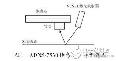
The working diagram of ADNS-7530 is shown in Figure 1. When an object moves within the lens collection distance, the laser emitter VCSEL emits laser light to the surface of the object, and is received by the sensor after being reflected. The surface image of the continuous object is obtained by optical principle, and then the object is automatically calculated according to the change information of the two images before and after. The direction and increment of surface movement are stored in the internal registers.
1.2 collection device
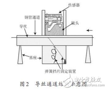
The guide wire channel device designed in this paper is mainly composed of steel pipe passage, sensor circuit board, base, spring baffle fixing device and the like. as shown in picture 2.
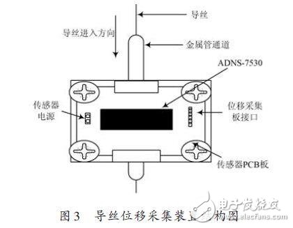
The guide wire displacement information collecting device is shown in FIG. The ADNS-7530 is soldered on the acquisition circuit board, the circuit board is fixed on the base, and the metal channel with the groove passes under the circuit board. The acquisition interface and the power interface on the circuit board are respectively connected with the external MCU pins and the power supply. connection.
1.3 acquisition circuit design
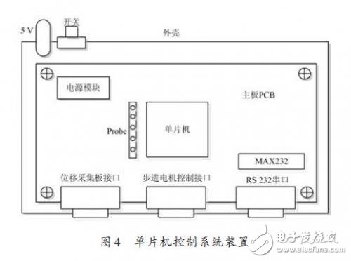
In the displacement information acquisition device, the acquisition circuit is mainly a communication circuit between the ADNS-7530 and the single chip microcomputer, including the initialization operation of the register in the sensor by the single chip microcomputer, and the real-time displacement information of the guide wire collected by the sensor; The serial communication circuit of the upper computer software system, the single chip computer packs the displacement information and sends it to the upper computer through the serial port. When the ADNS-7530 sensor collects displacement information, it stores the displacement information in binary form in the internal registers Delta_X_L, Delta_Y_L, and Delta_XY_H. The MCU reads the displacement data in the above registers through SPI. The ADNS-7530 should work normally. To accurately collect the displacement information of the guide wire, the internal registers must be configured in a certain order. As shown in Figure 4.
PCB universal screw terminals have been playing an important role in the electronic industry, and have become an important part of printed circuit board. The structure and design of the utility model are more solid, which has the characteristics of convenient and reliable connection of screws; the utility model has the advantages of compact structure, reliable connection and its own advantages; the utility model uses the lifting principle of the clamp body to ensure reliable connection and large connection capacity; the welding foot and the clamp body are divided into two parts, so as to ensure that the distance when the screws are tightened does not transmit to the welding points and damage the welding points; the shell is solid and reliable, and the needle distance is accurate.
PCB universal Screw Terminal Block , The design of the structure has the advantages of easy connection and reliable screw connection,suit for 0.08mm² to 35mm² wire connection with 2.5mm to 15.0mm pitch.
PCB Universal Screw Terminal Blocks
Screw Terminal Block,PCB Screw Terminal Block,Screw Terminal Connector,Screw Terminal Block Connector
Suzhou WeBest Electronics Technology Co.Ltd , https://www.webestet.com