The answering device is designed to create an electrical system capable of accurately identifying the responder, as the name suggests. In knowledge contests, cultural and recreational events (such as competition rounds), it allows for the accurate, fair, and intuitive determination of the respondent's seat number. This enhances the sense of competition among various groups and helps participants experience the pressure of a competitive environment.
Traditional responders only determine whether a player has answered correctly or committed a foul, without showing the time each player took to respond. The modern responder, however, uses data to explain the accuracy and fairness of the results. This makes the game more entertaining and also more just. The introduction of wireless responders marks a significant advancement in the history of such devices.
**PLC Controlled Responder Design One**
This design features a three-group responder system, where the host controls the game through buttons on the console. To ensure transparency in scoring and make it easier for the audience to understand each group’s performance, the responder must have appropriate display functions. The key functional requirements are as follows:
1. Before the game starts or before a new question is announced, the host must press the reset button to turn off all indicator lights.
2. To manage the game time, answers must be completed within 14 seconds. If no one answers within two seconds after the host announces the question, the question is invalidated. If a contestant presses the answer button within two seconds, the corresponding indicator light turns on, making the answer valid. After 14 seconds, the answering light turns off.
3. The first group to press their button will have their indicator light on, while the other groups' indicators remain off.
4. If the answer is correct, pressing the host's "correct" button will trigger a short piece of music and a small prize to be released from the prize box.
5. Only the group with the right to answer can receive points. At the end of the game, the winner is determined based on the number of prizes collected.
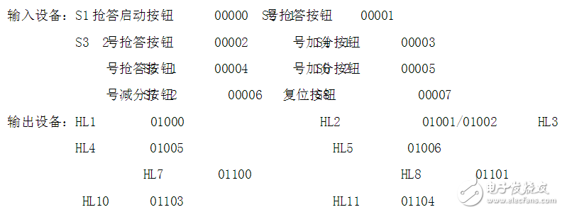
**I/O Port Allocation**
- **Input Ports:**
- 00000: SB – Host control grab button (Start)
- 00001: SB1 – First group answer button
- 00002: SB2 – Second group answer button
- 00003: SB3 – Third group answer button
- 00004: SB4 – Host control reset button (Stop)
- 00005: SB5 – Host control reward button (Correct answer)
- **Output Ports:**
- 01000: Output signal for the first group rushing
- 01001: Output signal for the second group rushing
- 01002: Output signal for the third group rushing
- 01003: Output timeout alarm signal
- 01004: Output correct answer signal
- 01005: Output bonus signal
**External Wiring Electrical Task Assignment:**
- KA1 controls group 1, locking out groups 2 and 3.
- KA2 controls group 2, locking out groups 1 and 3.
- KA3 controls group 3, locking out groups 1 and 2.
- KA4 controls the alarm lights.
- KA5 controls signal light A.
- KA6 controls the prize box B.
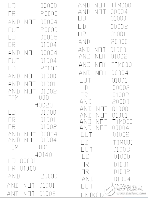
**PLC Control Responder Handheld Programmer Input Program**
The PLC-controlled responder handheld programmer input program is shown below:
**PLC Controlled Responder Design Two**
**PLC Responder Control Requirements:**
1. Before the host presses the answer button, players’ table lights flash for 4 seconds and then go out if they answer early.
2. If a player does not answer within 15 seconds after the host presses the answer button, the host’s desk light turns off, and the answer is invalid.
3. Once the host presses the answer button, the first player to answer will have their table light on, while others cannot answer until the current round ends.
4. After a player answers, they must complete their response within 40 seconds. If not, the table light turns off, and the host’s desk light turns on for 15 seconds before turning off.
5. Before each question, the host must press the reset switch to turn off all table lights.
6. If a player answers correctly, the host presses the bonus button to turn on the corresponding score light. If incorrect, the score light is turned off. The score remains unchanged after the reset.
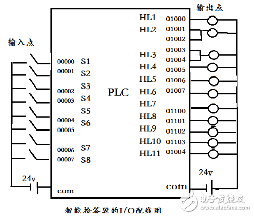
**Hardware Design – I/O Wiring Diagram**
**Software Programming and Machine Debugging Process**
Based on the I/O wiring diagram, we used OMRON software for programming. We mainly added time and counting procedures, as shown in Appendix 1. During the debugging process, we encountered some issues:
1. When connecting hardware to the PLC, some input/output points were unresponsive. After checking the hardware and data, we found an error in the power wiring of the common terminal. After fixing this, the system met the expected requirements.
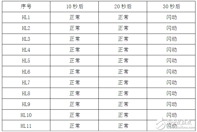
2. After transferring the program to the PLC, we observed that the signal lights changed according to the timeline as shown in the following figure:
**PLC Controlled Responder Design Three: Four-Way Responder**
This four-way responder is designed for up to four teams to compete simultaneously. Each responder includes a green 24V DC indicator and a jog button. The reset and start buttons are controlled by the host, who also has three display lights.
1. The responder is identified by an indicator light. Before the host presses the start button, players press their buttons. At this point, the player’s green light turns on, and the host’s red light indicates that the player who pressed early has been penalized. The question is then given to the next team. The host resets the system for the next question.
2. The responder has a timing function. After the host presses the start button, the green light indicates that players can begin answering. If someone answers within 20 seconds, their green light stays on. The responder has a self-locking feature, so only the first player to answer gets their light on. If no one answers within 20 seconds, the host’s yellow light flashes as a reminder. If no one answers within 25 seconds, the host’s red light turns on, indicating the question is invalid. If a player presses again, the green light remains off. After the host declares the question invalid, the reset button is pressed to prepare for the next question.
**Control System I/O Allocation Table**
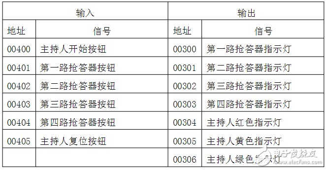
The I/O ports of the PLC are the connection points between the input and output modules and the external devices. In this design, I have created 6 input points and 7 output points. Since my maximum input and output are seven, I selected the eight-bit input and output module of the OMRON C200He model.
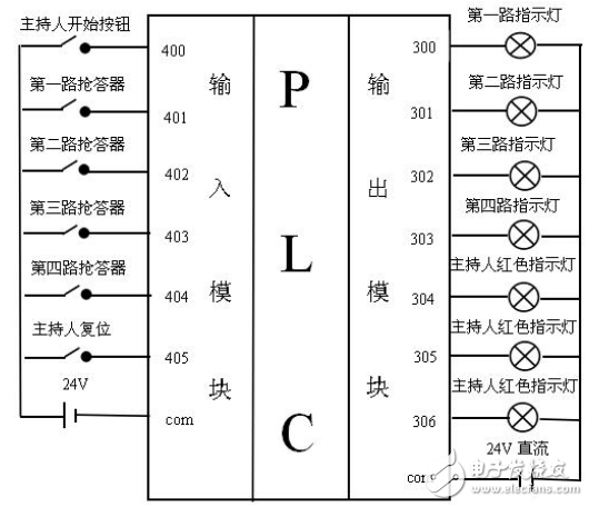
**Hardware System Connection Diagram**
The PLC device is connected like adding a module to a standard circuit. Different types of PLCs have varying numbers of input and output modules. Since its wiring only involves the common terminal and power supply, the connections are simple, which is a major advantage over traditional relay systems. The wiring for the 6 input and 7 output ports is shown below:
Disposable E-Cigarette 18000,Disposable E Cigarette 18000 Puffs,Disposable E Cigar with 18000puffs
Longhua Manxueling Trading Company , https://www.mxlvape.com