Abstract: This paper proposes a "total distribution, partial centralized" car door ECU design, and CAN bus communication between ECUs. The hardware circuit of the door ECU was designed with Infineon's XC164CS microcontroller and TLE8201 and BTS781 power driver chip as the core. The μC/OS-II real-time operating system was transplanted on XC164CS. Based on this, the task division and application were carried out. Software design, and finally built the experimental bench of the entire door control system. The test results show that the system runs stably and reliably and achieves design performance.
With the rapid development of technology, in order to improve the comfort of driving, a fully distributed control scheme based on bus systems such as CAN and LIN has been designed for the door control system of the car.
The car door electronic controller is a module that must be installed in every modern car. The basic configuration of the car door includes electric windows and central locking (door lock), front door mirrors, turn signals, courtesy lights, etc. These functions can be relatively independent and can be tailored to increase or decrease according to user needs. Due to advances in electronic technology and the development of integrated circuit manufacturing processes, the current mainstream of electronic modules for door modules is based on highly integrated chip control. Based on the high integration dedicated gated chips TLE8201 and BTS781 produced by Infineon, this paper presents a new door control solution.
1 door ECU overall design
Two door ECU solutions are currently popular, namely centralized control solutions and distributed control solutions. Among them, centralized control is to concentrate the control of power windows, mirrors, door locks and other loads by the vehicle body central controller, which can reduce the overall cost, but increase the complexity of the controller; and the control is too concentrated, size Larger, not conducive to installation, wiring and heat dissipation. The distributed control scheme is adopted by automobile companies such as Audi and Volkswagen. The load in each door is controlled by the respective ECU module, and can also be controlled by the driver side ECU through the CAN bus. In this scheme, two front door ECUs are connected to the CAN bus network, and the ECUs of the rear two doors can communicate with each other via the CAN bus or the LIN bus, or directly by the body controller module. The distributed scheme is simple to control, but the cost is high.
Drawing on the advantages of the above two control schemes, the research team designed a “overall distribution, partial centralized†control scheme. The block diagram is shown in Figure 1. The control of the left and right doors is used as an ECU module. The control of the front and rear two doors is used as another ECU module, and the CAN bus is connected between the two modules and between the module and the central controller. 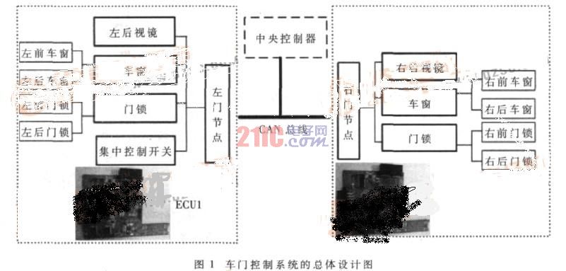
The design is cost-effective, easy to route and control, and is a compromise based on the advantages of centralized and distributed control. The central controller module in this design can simulate special diagnostic or information display functions and can be used to verify the correctness of the design. The actual door control node does not include this module.
2 door ECU hardware design
The hardware structure block diagram of the door control system is shown in Figure 2. The microcontroller used in this system is XC164CS produced by Infineon. Its MAC unit adds DSP function to process digital filtering algorithm, which greatly shortens the time of multiplication and division operation; five-stage pipeline structure, most single-cycle instructions, PEC transmission that can traverse the address space improves system performance. On-chip debug system (OCDS) supports debugging of the target system. The outstanding performance of the XC164CS is also suitable for the migration of real-time operating systems. 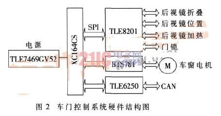
The TLE8201 is a new high-integration chip dedicated to door control from Infineon. The chip has six half-bridge circuits and five separate high-side switches. This multi-MOS tube integrated power chip has different on-resistances for its MOS transistors, which can be used to drive different power loads. For the door control module, the control functions of the door lock, the XY direction of the rear view mirror, the folding of the rear view mirror, the defrosting of the rear view mirror, the door light, etc. can be completed, and the protection and diagnosis functions are perfect.
The power drive chip BTS781 completes the lifting drive control of the electric window. The four MOS tubes of the BTS781 form an H-bridge circuit, which can easily realize the positive and negative control of the DC motor, and has perfect protection and fault diagnosis functions. These features ensure the reliability of the window motor control.
The TLE6250 is a CAN transceiver that is the CAN communication interface between the ECUs.
In the circuit design, the TLE8201 and BTS781 chips are mainly designed as the core to match the software to complete the corresponding load driving function. The circuit design with TLE8201 as the core is shown in Figure 3 (each ECU is controlled by two TLE8201 to control the front and rear door locks, mirrors and lights). The circuit design with BTS781 as the core is shown in Figure 4. Each ECU is controlled by two BTS781 to control the window of the front and rear doors respectively). It can be seen from Fig. 3 that the door lock, the rear view mirror and the lamp control circuit with the TLE8201 as the core are very simple, which reduces the circuit board area and improves the reliability. The window lift control circuit with BTS781 as the core can realize the window anti-pinch function by software detection and filtering amplification of the window motor. The right ECU unit is similar in design to the left ECU unit. 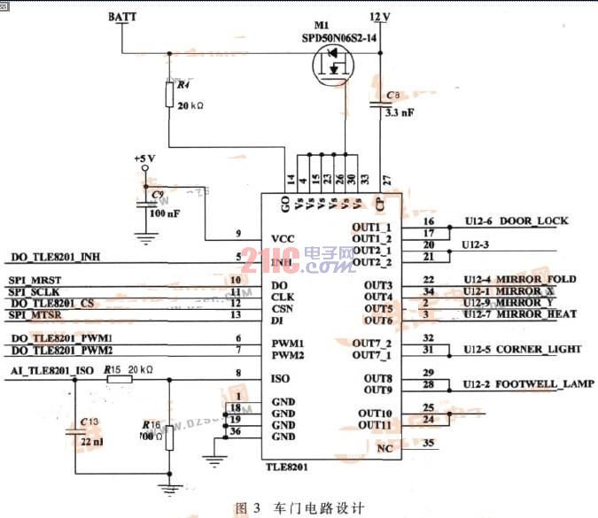
3 software design
Migration of 3.1 μC/OS-II real-time operating system on XC164CS microcontroller
The door ECU of this system adopts the design method based on μC/OS-II real-time operating system. After the completion of the μC/OS-II migration, the application programming can be greatly simplified, debugging, maintenance and porting can be facilitated, the stability of the system can be improved, and various functions can be tailored according to the needs of the user, and new functions can be easily added and shortened. Development time. Therefore, the door ECU design of this system must first complete the transplantation of μC/OS-II on XC164CS, and then complete the application software design of the whole ECU by task addition. 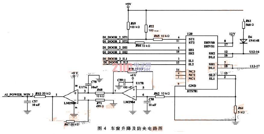
The so-called porting is to enable a real-time kernel to run on a microprocessor or microcontroller. Although most of the μC/OS-II code is written in C, you still need to write some processor-related code in assembly language, because μC/OS-II can only pass through the processor registers. Assembly language to achieve.
For μC/OS-II to function properly, the processor and its compiler must meet the following requirements:
(1) The processor's C compiler can generate reentrant code;
(2) The interrupt can be turned on and off in C language;
(3) The processor supports interrupts and can generate timing interrupts (usually between 10 Hz and 100 Hz);
(4) The processor supports a hardware stack that can hold a certain amount of data (possibly several kilobytes);
(5) The processor has instructions to read and store the stack pointer and other CPU registers onto the stack or memory.
The XC164CS microcontroller and the Keil C166 compiler meet these requirements. The migration work focuses on how to make the μC/OS-II correctly define and use the XC164CS. The first is the interrupt handling mechanism of the chip, that is, how to open and mask the interrupt, and whether to save the previous interrupt status. In addition, you need to pay attention to the system's use of memory, such as memory address space, stack growth direction, push and pop instructions.
Specifically, since most of the code for μC/OS-II itself is written in ANSI C code, and the hierarchy of the code is very simple, the platform-related porting code exists only in OS_CPU_A.ASM, OS_CPU_C.C, and Among the three files OS_CPU.H. Therefore, the migration work involves these three files, and the corresponding code modification has been completed, and the migration of C/OS-II on the XC164CS has been completed.
3.2 Door ECU task division and task addition
This design divides the control tasks into the four main tasks shown in Table 1. 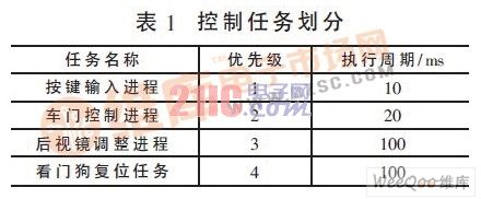
According to the above tasks, the software structure block diagram of the design system is shown in Figure 5. 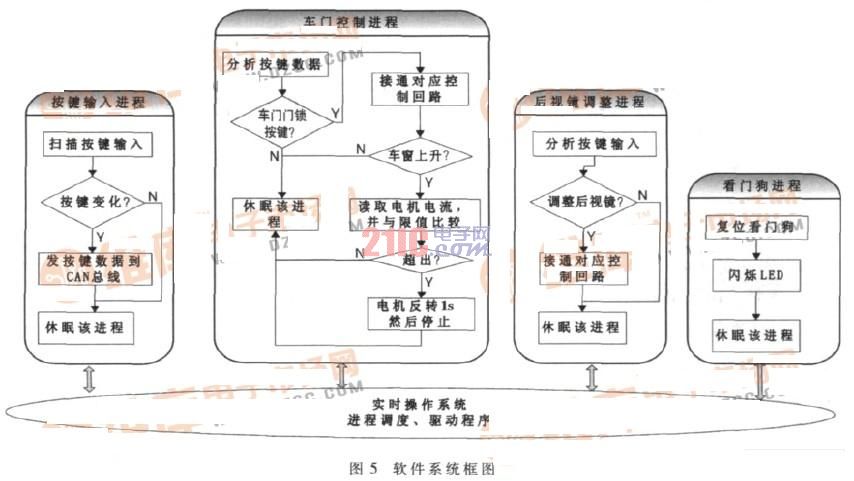
According to the above design scheme, this project designed a “total distribution, partial centralized†car door system control scheme. The test results show that the designed door control system can fully realize the control functions of window lift (with anti-pinch control), rear view mirror XY direction control and folding, door lock switch and so on. The system has been tested for a long time, working normally and reliably, and has achieved the expected design goals.
This article refers to the address: http://
The accessories are very important in using and installing, so we offer the driver,controller,Mounting Brackets,and led strip caps.Use the driver to support the led strip lights,because the led strips are low voltage. If there needs color change or adjusting brightness,the RGB controller or dimmer can make it real.In order to make the installation easy, the unique brankets are optional.Each evenstrip has matched bracket.If the length of led strip needs to cut short,use the plastic end caps to keep waterproof.
Strip Light Accessories,Waterproof Led Driver,Led Strip Light Controller,Led Strip Cap
Guangdong Kamtat Lighting Technology Joint Stock Co., Ltd. , http://www.ip68ledstrip.com