Abstract: The MAX9217/MAX9218 serializer and deserializer chipsets enable video data transmission over a pair of twisted-pair LVDS links for automotive and industrial applications. There is always a blanking period for each frame of the video signal that can be used to "carry" the audio data. In this application note, we discuss the transmission format of audio data, the method by which video links transmit data, and specific examples of system implementation.
This article refers to the address: http://
introduction
The MAX9217 /MAX9218 chipset [1] is a transceiver pair. The transmitter (MAX9217) converts parallel data into serial data for transmission to the receiver (MAX9218); the receiver converts the serial data to parallel data. The chipset is designed to transfer video and control signals from a graphics controller (processor) to an LCD or plasma flat panel display via a pair of low-cost twisted-pair cables (eg, UTP-CAT5 cables commonly used in Ethernet). . The transmission distance can exceed 10 meters. The chipset has a simple link structure, and the transmission line used is a low-cost cable, which is an ideal solution for video display of automobiles, meters, medical devices, and the like.
The chipset can not only transmit video signals between two points, but sometimes it is desirable to transmit audio signals at the same time. In this application note, we will discuss how to use the blanking period of a video signal to transmit audio data to the display through a control signal path. We will also explain how to convert digital audio data into analog audio signals and give the system structure of the display panel-side speaker driver.
MAX9217/MAX9218 link function and video data format
The MAX9217 serializer features a 27-bit parallel input with a bus speed of up to 35Mbps. Among these 27 bits, 18 bits are video RGB data: 3 primary colors each occupy 6 bits, and the remaining 9 bits are control signals. The first 3 bits of the 9-bit control signal are designated for vertical, horizontal, and RGB data synchronization: VSYNC (C0), HSYNC (C1), and ENAB (C2). The remaining six control bits (C3 to C8) are used for other control signals. In this example, we use a portion of the 6 control bits to transmit audio data. The MAX9217 converts 18-bit RGB data or 9-bit control data into serial data and transmits it over an LVDS link. The control data is transmitted during the blanking period of the video display and is indicated by the RGB data enable signal (ENAB).
After receiving the serial data, the MAX9218 converts it to the same parallel data as the MAX9217 input format. Similarly, when the MAX9218 outputs parallel data, the bus clock is regenerated based on the timing of the serial LVDS link. Figure 1 shows the block diagram of the video and control data link setup and connections between the MAX9217 and the MAX9218. Figure 2 shows the timing of video data and control data. Depending on the video format, display resolution, and link rate, the control duty cycle for RGB data is between 1% and 5%. 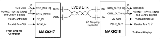
Figure 1. Video Link Settings for the MAX9217/MAX9218 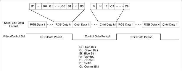
Figure 2. Video data and control data format for a serial link
Digital audio data type and transmission format
Digital audio data comes in many different formats. We discuss the three most commonly used formats: Sampled Digital Audio (PCM), MPEG Layer 3 Audio (MP3) [2], and ATSC Digital Audio Compression Standard (AC3) [3].
PCM digital audio is the data format used by CD ROM or DVD. The audio signals of the left and right channels are sampled to obtain a PCM digital signal with a sampling rate of 44.1 kHz and an accuracy of 16 bits or 32 bits. Therefore, when the accuracy is 16 bits, the PCM audio data rate is 1.41 Mbps; when it is 32 bits, it is 2.42 Mbps. A 700MB CD can hold up to 60 minutes of music in 16-bit PCM data format.
MP3 is an audio format used by MP3 players to compress and encode PCM audio data. Stereo MP3 data rates range from 112kbps to 128kbps. For this data rate, the decoded MP3 sound effect is the same as the quality of the CD digital audio. AC3 is a digital TV, HDTV and cinematic digital audio coding standard. The data rate after stereo AC3 encoding is 192 kbps.
In order to recover the audio signal, the encoded audio data can be sent to an audio decoder chip, which generates PCM digital data, which is transmitted to an audio DAC and finally restored to an analog audio signal. In contrast, unencoded digital audio data can be sent directly to the audio DAC. (This type of system implementation is detailed below.)
A common serial audio digital interface for encoding or decoding audio data is the Inter-IC Audio Bus (I2S) [4]. Figure 3 shows the I2S interface configuration and timing diagram. The boundary of each audio word is identified by the signal WS. Configuration mode 1 is used in our application. At the rising edge of the SCK signal, the data is latched to the receiver, but when SCK is held low, no data is received. 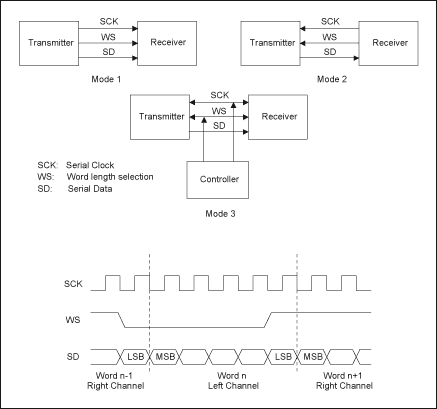
Figure 3. I2S interface configuration and timing
Using the serial link between the MAX9217 and the MAX9218 to emulate the I2S interface, audio data can be transferred from the graphics controller to the far end. We assign control bits C3 and C4 to the SD and WS signals, respectively. For the SCK clock, if you want to send PCM digital audio, you can use the pixel clock PCLK_OUT recovered by the MAX9218. For transmitting MP3 or AC3 audio, control bit C5 can be used to generate a half or lower rate pixel clock for the SCK clock. Figure 4 shows the timing waveforms for both cases. In order to prevent the receiver from overflowing, most I2S interfaces need to perform throttling control. When data is continuously transmitted, SCK can be set low to directly implement throttling control. In Case 4 in Figure 4, the SCK signal cannot be deasserted during operation. The chip select pin /CS can be used to turn off the receiver. In this case, Case 1 in Fig. 4 assigns C6 to the /CS signal. 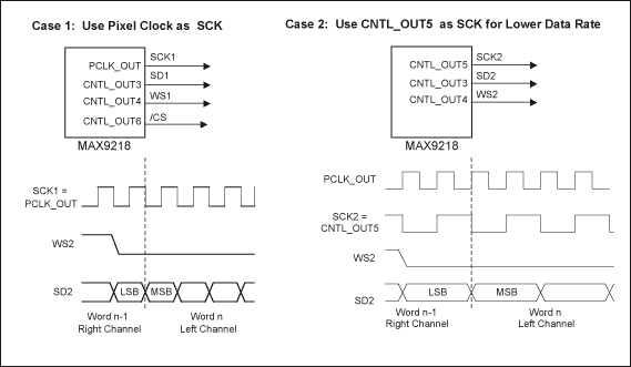
Figure 4. Control data bit waveform for the I2S interface
Blanking ratio and audio data throughput
Since the audio data blanking period of the video signal is transmitted through, we need to determine whether a given pixel frequency f P ratio and the line-blanking blanking ratio. Figure 5 shows the line blanking and field blanking periods on the display panel. 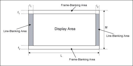
Figure 5. Line blanking and field blanking
The line blanking ratio is represented by RL, and the field blanking ratio is represented by RF. As shown in Fig. 5, we can calculate these ratios according to the following formulas:
R L = (I 1 + I 2 ) / L
with
R F = (f 1 + f 2 ) / F
The audio data throughput rate R A is thus obtained, namely:
R A = (R F δ F + (1 - R F ) R L δ L ) f P
Where δF and δL are the audio data transmission utilization rates in the blanking period. Utilization refers to the proportion of audio data transmission in the entire blanking period, which is the result of throttling control. As an example, the parameters shown in Table 1 set the data rate for three types of audio data.
Table 1. Blanking parameter settings for different types of audio data
| Audio Data Type | f P | R A | R B | Data Rate | ||
| 16-Bit PCM Audio Data | 35 | 0.02 | 0.03 | 81% | 82% | 1.41Mbps |
| MP3 | 17.5 | 0.01 | 0.01 | 35% | 38.5% | 128Kbps* |
| AC3 | 17.5 | 0.01 | 0.01 | 50.3% | 60% | 192Kbps* |
*Note: Both MP3 and AC3 audio data contain header files. With this information in mind, the actual encoded data rate will be slightly higher [2, 3].
System implementation
To play the audio signal on the panel side, we need to send the PCM data to the audio DAC or decode the MP3 and AC3 data and send it to the audio DAC. Since there is no reverse channel to send the handshake signal back to the controller, the decoder master clock must be synchronized with the pixel clock to prevent data overflow or underflow. Figure 6 shows a system block diagram of audio playback of encoded and unencoded data. 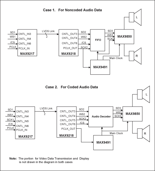
Figure 6. Panel-side audio playback implementation
In the above structure diagram, three I2S interfaces are used. Starting from the left, the first and second I2S interfaces have the same data rate and can reach 35MHz. The third interface, the MAX9850 DirectDrive Headphone Amplifier [5] interface, has a fixed rate that is a multiple of the audio sample rate. Clock SCK2 is fed into the MAX9491 multiplex clock generator [6], which generates the decoder, FIFO, and MAX9850 synchronous clock. The MAX9491 offers two programmable PLLs with OTP and is the ideal frequency synthesizer for this application. Case 1 is suitable for providing graphics controllers for decoding PCM audio data, and Case 2 is for decoding of compressed data on the panel side. Case 1's throttling control is implemented by the /CS pin, and Case 2 is implemented by the idle SCK clock. Comparing these two implementations, we see that Case 1 of PCM audio data does not need to occupy too much blanking time (Table 1), and does not require the use of an audio decoder chip, and the cost is lower than Case 2. Therefore, if the graphics controller is capable of generating PCM data from an encoded audio data stream such as MP3 or AC3, it is recommended to transmit the data directly on the link.
Centrifugal pump refers that pump which deliver the liquid depend on centrifugal force generated by the rotation of the impeller. Before the water pump start, we must make the pump case and suction pipe full of water, then launch the motor, make pump spindle drive impeller and water to do high speed rotation motion, water takes place centrifugal movement, be thrown to the outer edge of the impeller, through the water channel of the volute pump case flow to the Pressurized water pipe of the water pump. Centrifugal pump can be widely used in liquid transfer.cooling system and so on.
Brushless Centrifugal Water Pumps
Brushless Centrifugal Water Pumps,Brushless Water Pump,Cooling Tower Water Pump,Brushless Cooling Pump
Dongyuan Syscooling Technology Co., Ltd. , http://www.syscooling.com