0 Introduction Intelligent vehicles are the forefront of research in the field of vehicle engineering. It embodies the intersection and integration of theoretical technologies in many disciplines such as vehicle engineering, artificial intelligence, automatic control, and computer. It is the trend of future automobile development. In the past, smart cars used single-program control in software design, which is not conducive to the rapid response of smart cars when the external environment changes. In order to make the smart car system react more quickly, the smart car uses μC/OS-II system, the system Suitable for small control systems, featuring high efficiency, small footprint and excellent real-time performance. The AVR series ATmega16 single-chip microcomputer with lower power consumption and richer resources is selected as the core control unit.
The infrared detection method is used to realize the tracing function, that is, the infrared photoelectric sensor is fixed at the front edge of the chassis, and the surface of the object with different colors has different reflective properties, and the infrared light is continuously emitted to the ground during the driving process of the trolley, and the single chip is The reflected infrared light is received as a basis to determine the position of the black line and the walking path of the trolley. And evenly distributed black and white stripes on the rear wheel, according to the photoelectric reflection principle, the vehicle speed is measured. In order to ensure that the smart car has good stability and smoothness during the driving process, the control system provides an ideal solution for DC motor drive control.
This article refers to the address: http://
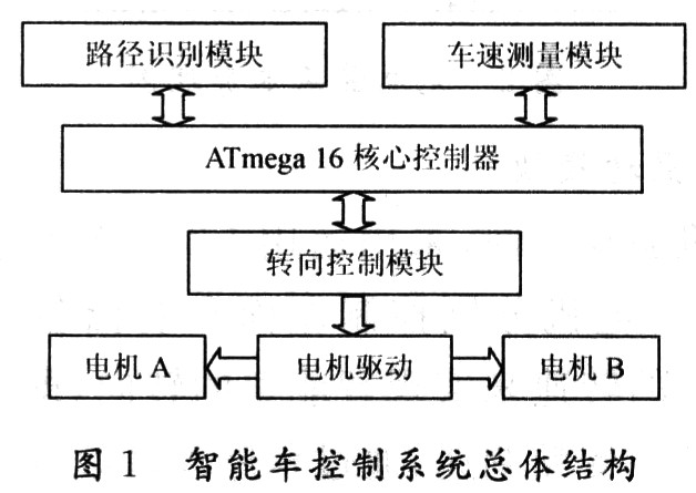
1 hardware system design and implementation of the hardware part of the smart car with AVR series ATmega 16 microcontroller as the core controller, from the core control unit, power management module, path identification module, steering control module, motor drive module and speed and distance detection module composition. The overall structure of the intelligent vehicle control system is shown in Figure 1.
1.1 Core Control Unit The smart car adopts the ATMe 16 type MCU as the main control CPU. Its main features are high performance, low power consumption, high cost performance, rich resources, and support for high-level language programming at running speed. Memory capacity, integration of internal functional modules and many other aspects are more advanced than the MCS-51 series. In the design of the smart car system, the I/O resource allocation of the MCU is as follows: PB3, PD7 is the PWM control signal output pin of the servo motor; PD0~PD3 are the positive and negative pins of the drive motor; the path identification system is routed by PA0 ~PA6 input to the microcontroller.
1.2 Power Management Module In order to avoid interference from the system such as the motor, the functional modules of the smart car are powered separately. The 12 V battery is used to supply the DC motor, and the 12 V voltage is stepped down and regulated to supply power to the MCU system and other chips. Compared with other types of power supplies, the battery has strong current drive capability and stable voltage output performance. Considering the large size of the battery, there is enough space in the design of the car body.
During voltage regulation, two 7812 chips are used to regulate the voltage to 12 V, then the DC motor is powered, and then the voltage is stabilized to 5 V with 2576. The 2576's output current can be up to 3 A, which fully meets system requirements.
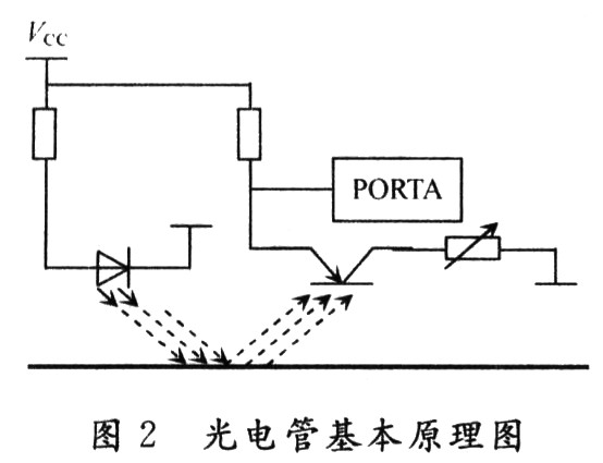
1.3 Path Recognition Module The intelligent vehicle adopts the infrared detection method to realize the walking of the trolley on the black floor by white line. In order to improve the control precision, the sensor is required to be arranged closely and as close as possible. However, the sensors are closely packed and the light from the sensor's launch tube may be reflected from the ground into the receiving tube of the adjacent sensor. In order to eliminate the mutual interference between the sensors, the sensor is divided into 7 groups, and the 7 I/O ports PA0 to PA6 are directly used by the MCU to read the sensor data. The infrared light has different reflective properties on the surface of objects of different colors. During the driving process of the smart car, the sensor continuously emits infrared light to the ground, and when the infrared light encounters the white paper floor, diffuse reflection occurs, and the reflected light is mounted on the surface. The receiving tube on the trolley receives; if it encounters a black line, the infrared light is absorbed, and the receiving tube on the trolley does not receive infrared light (the schematic diagram is shown in Figure 2). The MCU determines the position of the black line and the walking path of the car based on whether the reflected infrared light is received.
1.4 Motor drive module In the motor drive, the L298 is used as the motor drive chip, and the two motors A and B respectively control the two wheels on the left and right sides. The steering of the smart car is realized by adjusting the rotational speed of the two wheels, that is, the PWM frequency conversion speed regulation is controlled by the single chip microcomputer, and the duty ratio of the pulse width adjustment waveform is changed by the program design, thereby realizing the speed regulation. When the steering angle is different, the difference in the rotational speeds of the two motors is different. When the car is in a large deviation state, the speed of one motor needs to be adjusted to a very low level, and the other motor is operated at full speed, thereby completing the adjustment of the route in a short time.
Control the forward and reverse of the smart car by setting the forward and reverse rotation of the motor. This circuit design is simple and efficient, and ensures two-wheel synchronization.
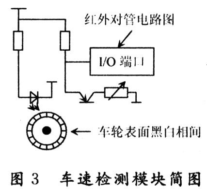
1.5 Vehicle speed detection module The intelligent vehicle system reads the real-time vehicle speed through the vehicle speed detection module. A method of uniformly distributing black and white stripes on the rear wheel is used. The black and white stripes on the wheel are detected using the detection circuit of FIG. According to the photoelectric reflection principle, when the wheel rotates, the infrared receiving tube receives the intensity change of the reflected light, and a pulse signal corresponding to the wheel rotation speed is generated, and the pulse signal is amplified and shaped and input into the input capture pin PA7 of the single chip microcomputer. By recording the number of pulses obtained per unit time, the current vehicle speed can be indicated, and the distance traveled by the trolley can be calculated by accumulating.
2 Software system design and implementation In order to make the smart car respond more timely and accurately in the environment change, the μC/OS-II system is applied in the program design. The μC/OS-II is suitable for small control systems and features high execution efficiency, small footprint, excellent real-time performance and high scalability. The smallest core can be compiled to 2 KB. The μC/OS-II code is written in C and can be ported directly to a processor with a C compiler. The migration is mainly focused on the implementation of multitasking switching. Since this part of the code is used to save and restore the CPU field (that is, write/read related registers), it can't be used in C language, only in assembly language, that is, writing OS CPU A. S file. There is also a need to modify the OS CPU associated with the architecture. H file and user specified task stack initialization structure of OS CPU C. C file.
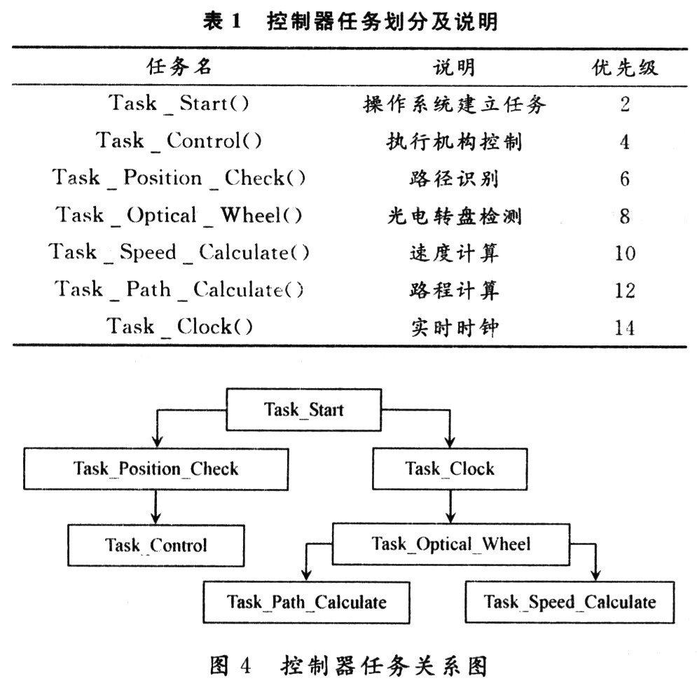
μC/OS-II is a deprived real-time multitasking kernel. The deprived real-time kernel runs the highest priority task at all times. In μC/OS-II, up to 64 tasks can be supported, corresponding to priorities 0 to 63, where 0 is the highest priority. In the system design, a total of seven priorities are applied, in which the operating system establishes a task, that is, Task Start() has the highest priority. Scheduling can be divided into two parts: the search for the highest priority task and the task switching.
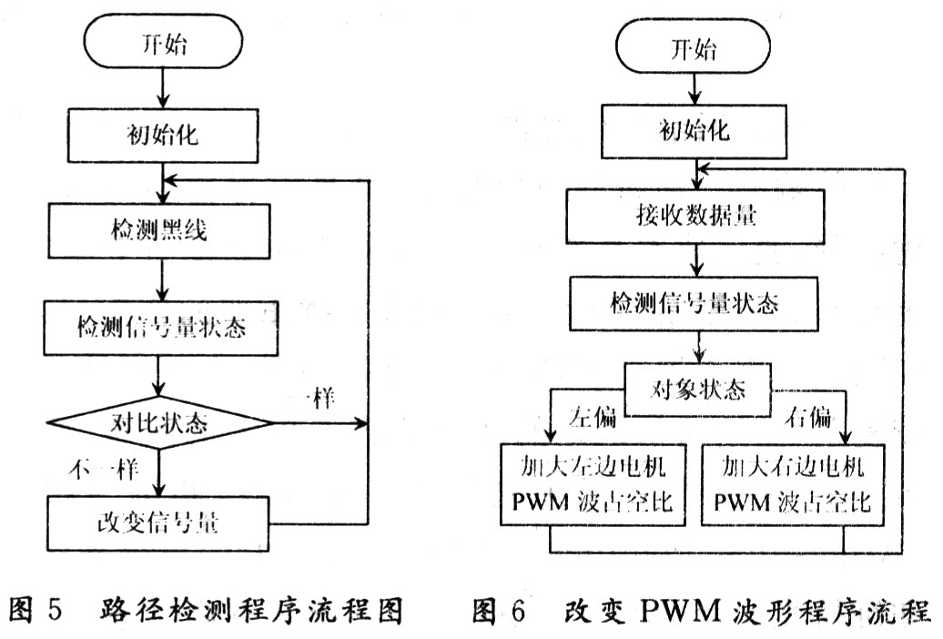
In this system, seven tasks such as path identification and photoelectric turntable detection are defined. The controller task division and description are shown in Table 1. The scheduling and communication implementation process is as follows: The system executes Task Start(). After the initialization task is completed, the task is returned to the sleep state by using the OSCAskDel() function of μC/OS-II. At this point, the Task Po-sition Check() becomes the highest priority task and will continue to execute. When the Task Position Check() detects a change in the path, the data is transferred to the Task Control() via the mailbox, and the change of the PWM wave output is controlled by the TaskControl(). Task Task Op-tical_Wheel() has a slightly lower priority and will always execute. When the task Task_Optical_Wheel() detects black and white transitions, the variable in the task is incremented by 1. Task_Optical_Wheel() is used every 1 s to the task Task_Path_Calculate(). And Task_Speed_Calculate () to send a message, calculate the speed and the accumulated distance, the controller task diagram shown in Figure 4.
2.1 Identification of path black line The accuracy of the identification of the path black line determines whether the smart car can complete fast and stable hunt. The identification device consists of a high-emissivity infrared photodiode and a high-sensitivity phototransistor. The non-contact detection method can adjust the detection distance by 4 to 20 mm. In order to accurately determine the relative position of the smart car, seven pairs of ST178 are placed side by side at the front end of the lower part of the chassis, and the distribution is perpendicular to the direction in which the smart car travels. When the car is walking, 7 light-emitting tubes are kept illuminated. When the lower side of a certain photoelectric pair tube is a black track, the corresponding receiving tube output is at a high level, and the receiving tube output below the white road surface is at a low level. After the data processing, the control system can analyze the current vehicle walking position, so as to achieve the purpose of adjusting the running state of the smart car. For example, suppose the width of the black line on the road surface is the width of three sets of infrared pair tubes. When the black line is in the middle of the vehicle body, the seven input pins are 28H (0011100); when the body is left or right, the received data is received. Will change, that is, "1" will move to the left or right, such as 0001110 (right bias), 0111000 (left bias), the offset amplitude is different, the number of shifts of "1" is different.
2.2 Steering control module adopts PWM (pulse width modulation) control, and uses L298 drive circuit to realize the speed regulation of DC motor. The method is simple and the speed regulation range is large. It uses the principle of DC chopping, assuming high level conduction. The conduction time is t in one period T, then the average voltage U=(t/T)VCC=qVCC in one period T, wherein the duty ratio q=t/T.
The speed of the motor is proportional to the voltage across the motor, and the voltage across the motor is proportional to the duty cycle of the control waveform. Therefore, the speed of the motor is proportional to the duty cycle. The higher the duty cycle, the faster the motor turns. When the duty cycle q=1, the motor speed reaches the maximum. The smart car system uses an 8 MHz crystal oscillator, and the frequency of the PWM signal pin OCRO/2 is: ![]()
Where: variable N represents the division factor: 1.8, 32, 64, 128, 256 or 1 024. The formula for calculating the duty cycle is:
t/T=(OCR0/1/256)
2.3 Vehicle speed and distance measurement module The black and white stripes are evenly distributed on the rear wheel of the smart car. During the rotation of the wheel, the infrared sensor continuously detects the appearance of black and white stripes. When the infrared sensor detects black streaks, the input voltage is high, and when the white streaks are detected, the input voltage is low. If the sensor detects a level transition, the count variable is incremented by one. The clock generates an interrupt every second. The Task_Clock() process sends data to the Task Speed_Calculate() process via the mailbox, which calculates the car speed: speed = data / number of stripes per circle. As shown in Figure 5 and Figure 6.
3 Conclusion This paper introduces the design and implementation of an intelligent tracking model car. Practice has proved that the smart car has accurate positioning, fast and stable system response, good dynamic performance and precise steering performance, which proves the effectiveness and stability of the μC/OS-II system. Compared with similar smart cars, the model car also has the advantages of high performance and low power consumption.
Heat-Shrink Tubing is a shrinkable plastic tube used to insulate wires, providing abrasion resistance and environmental protection for stranded and solid wire conductors, connections, joints and terminals in electrical work. Optical Fiber Protection sleeves are used for holding and protecting fusion fiber splice point . It can also be used to repair the insulation on wires or to bundle them together, to protect wires or small parts from minor abrasion, and to create cable entry seals, offering environmental sealing protection. Heat-shrink tubing is ordinarily made of nylon or polyolefin, which shrinks radially (but not longitudinally) when heated, to between one-half and one-sixth of its diameter.
Heat-shrink tubing is manufactured in a multitude of varieties and chemical makeups with the exact composition of each type being dependent on the intended application. From near microscopically-thin-wall tubing to rigid, heavy-wall tubing, each type has precise design and chemical additives that make it suitable for meeting any of a wide variety of environmental demands. Heat-shrink tubing is rated by its expansion ratio, a comparison of the differences in expansion and recovery rate.
Heat Shrinkable Tubing,Heat Shrink Sleeves,Heat Shrink Tubing,Heat Shrinkable Protective Tubing
Chengdu XingXingRong Communication Technology Co.,Ltd , http://www.xxrtx.net