With the continuous development of automotive electronic control technology, the number of automotive electronic equipment has increased greatly, the working frequency has gradually increased, and the power has gradually increased, making the working environment of the automobile full of electromagnetic waves, causing the electromagnetic interference problem to become increasingly prominent, and affecting the normality of electronic equipment. Work, but damage the corresponding electrical components. Therefore, the electromagnetic compatibility of automotive electronic equipment is receiving more and more attention. At present, it is urgent to apply electromagnetic improvement technology for automotive sub-devices.
Source of electromagnetic interference
Automotive electronic equipment works in cars with changing driving conditions. The complexity and variability of electromagnetic energy in the environment means that the system is exposed to a wide range of electromagnetic interference sources. According to the source classification of electromagnetic interference, it can be divided into electromagnetic interference outside the vehicle, static interference of the vehicle body and electromagnetic interference inside the vehicle.
External electromagnetic interference
External electromagnetic interference is the interference experienced by the vehicle when it experiences various external electromagnetic environments. This type of interference exists in a specific space or at a specific time. Such as high-voltage transmission lines, high-voltage substations and high-power radio transmission station electromagnetic interference, as well as lightning, sunspot radiation electromagnetic interference, and so on. Other nearby electronic devices in the environment can also cause interference when working, such as cars that are close together during driving.
Vehicle body static interference
The static interference of the car body is related to both the car and the external environment. Due to the high-speed friction between the car body and the air while the car is running, unevenly distributed static electricity is formed on the car body. Electrostatic discharge can form interference currents on the vehicle body, and at the same time generate high-frequency radiation, which forms electromagnetic interference to automotive electronic equipment.
In-vehicle electromagnetic interference
In-vehicle electromagnetic interference is the internal interference of automotive electronic equipment, including the electronic noise generated by electronic components, the electromagnetic interference generated by the commutating brush during motor operation, and the discharge interference during various switch operations. The most serious is the car. The high frequency radiation generated by the ignition system has the highest interference energy.
The path and principle of electromagnetic interference
Electromagnetic interference is classified according to interference channels, and is mainly divided into conducted interference, induced interference and radiated interference. The corresponding interference principle is as follows.
Conducted interference
Conducted interference mainly propagates through the common conductor of the circuit. The typical structure is the common power line and the common ground line. Figure 1 is a schematic diagram of a typical conducted interference circuit. R is the resistance on the power line, Z is the resistance on the ground, U is the branch voltage, and I is the branch current.
This article refers to the address: http://
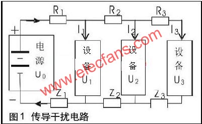
Because the working voltage of each device is

Therefore, any device current change will cause other equipment voltage changes and cause interference. To reduce the interaction between devices, you need to reduce the R, Z, and I values.
Inductive interference
Inductive interference is divided into two types: electrical induction interference and magnetic induction interference. The basic circuit diagram is shown in Figure 2 and Figure 3. U1 is the voltage of the wire 1, I1 is the current on the wire 1, U2 is the interference voltage on the wire 2, C12 is the capacitance between the two wires, C1g and C2g are the capacitance of the wire 1, the wire 2 and the ground, and M12 is between the two circuits Mutual inductance, R is the resistance of each circuit.

For the induction circuit,  To reduce U2, you can reduce C12, U1, and R, or increase C2g. The first measure is to reduce C12 by increasing the wire distance or changing the dielectric parameters between wires. For magnetic induction circuits,
 ![]() To reduce U2, you can reduce M12 or reduce the rate of change of I1. The basic measure is to reduce M12. For a typical two-loop,
To reduce U2, you can reduce M12 or reduce the rate of change of I1. The basic measure is to reduce M12. For a typical two-loop,  L1 and L2 are two loop lengths, m0 is vacuum permeability, and r is the distance between two loop conductor segments. Therefore, increasing r and reducing the loop area can reduce M12.
Radiation interference
Radiated interference is transmitted by the antenna, and since the energized wires and cables can be regarded as equivalent antennas, the harness radiation interference of the automotive electronic equipment is very serious. According to the Maxwell equation, the radiant electromagnetic field of a typical monopole antenna is 
![]()
For the spherical coordinates, I is the antenna current, l is the antenna length, r is the distance from the antenna to the field point, w is the angular frequency, e0 is the air dielectric constant, and l is the electromagnetic wavelength. To reduce H and E, you can reduce I, l, or increase r.
In summary, the electromagnetic interference outside the vehicle decreases with the increase of the working distance, and only when its own energy is very large, it can affect the electronic equipment that is far away. The results of many years of research indicate that the electromagnetic effect of large energy is harmful to human health. Various electromagnetic standards have been formulated to limit such interference, and the influence of automotive electronic equipment is reduced.
The vehicle body static interference and the electromagnetic interference inside the vehicle, because the interference effect distance is short, the interference time is long, and the interference intensity is relatively large. Since the automobile electronic equipment forms an electrical network with the battery and the alternator as the core power source and the vehicle body as the common ground, each part of the wire harness will conduct interference with each other through the power source and the ground line, and the adjacent wires have inductive interference, and are not adjacent. The wires also radiate interference due to the antenna effect, which makes the interior interference integrated into three ways, the interference composition is more, and the coverage frequency is wider, which is the main electromagnetic interference of the automotive electronic equipment. Solving these two kinds of electromagnetic interference problems can simultaneously improve the anti-interference ability of automotive electronic equipment to electromagnetic interference outside the vehicle, thereby reducing the possibility of malfunction or damage of the equipment.
Measures to improve the electromagnetic compatibility of electronic equipment
The electromagnetic compatibility of automotive electronic equipment includes two aspects, one is electromagnetic emission, which measures the emission level of electromagnetic interference generated by the system; the other is electromagnetic sensitivity, which measures the ability of the system to resist electromagnetic interference when it is working to achieve the expected technical specifications. . According to the previous analysis, to comprehensively improve the electromagnetic performance of automotive electronic equipment, it can be considered from three aspects, one is to reduce the intensity of electromagnetic interference emitted by equipment; the second is to suppress the transmission of electromagnetic interference; the third is to reduce the interference of electromagnetic sensitive components of equipment. strength.
Reduce the electromagnetic interference intensity of the device
Optimize the electrical structure of the device: In the electronic device of the automobile, the flasher is a relay contact structure, and an arc suppressor can be added in front of the contact; the motor is an inductive load, and the current noise can be reduced by the internal filter circuit; the printed circuit of various electronic control units Board, to optimize wiring, reduce the level of electromagnetic emissions.
Choose the right electronic components: various control units on the car, using lower frequency chips to help reduce radiation interference.
Reduce the power of the device: Reduce the power of the device to meet the functional requirements, reduce the interference voltage and current, and thus reduce the interference intensity.
Interference-inhibited transmission
Shielding interference source equipment and related wiring harnesses: The electronic control unit used in the main electronic control system of the vehicle should be packaged in a shielded housing.
Adding harness filtering: For longer harnesses, to reduce conduction and radiation interference, filter should be added to the harness. It is convenient to sleeve the appropriate ferrite ring.
Reasonable planning of the wiring harness: The wiring harness arrangement makes the small power sensitive circuit close to the signal source, the high power interference circuit is close to the load, and the small power circuit and the high power circuit are separated as much as possible to reduce the inductive interference and radiation interference between the wiring harnesses.
Improve grounding of equipment: Good grounding and improved grounding can reduce high frequency impedance. The grounding of automotive electronic equipment is mainly connected to the vehicle body and the wiring layer of the wiring harness.
Reduce the intensity of the device receiving interference
Reduce the area where the equipment receives interference: The wiring harness should be designed to have the minimum length, minimum impedance and minimum loop area. It is best to use a power supply with a small loop area such as twisted pair. Increase the distance from the device to the interference source: In the case of the same arrangement of the interference device, modify the installation position of the sensitive component and increase the distance to the interference source.
Experimental study on electromagnetic compatibility improvement measures
At present, electromagnetic compatibility simulation calculations are usually used to make a preliminary estimation of the electromagnetic properties of the vehicle body structure. The electromagnetic performance of automotive electronic equipment is mainly based on testing, so the improvement measures are focused on experimental research. According to the Electromagnetic Compatibility Regulations of Vehicles and Components, GB18655-2002 "Limitations and Measurement Methods for Protecting Radio Disturbance Characteristics of Vehicle Receivers", electromagnetic compatibility tests are carried out on electronic equipment of a commercial vehicle model in China. Comprehensive improvement measures have been adopted, and the test results can compare the effects of various measures in real vehicle operation.
Structural adjustment and internal filtering of the wiper motor
The wiper motor is a typical inductive load interference source in the equipment. The power is large. It is measured by the component test method. The commutator structure of the motor is adjusted first, and the circuit is filtered inside the motor. Figure 4 and Figure 5 show the results before and after the improvement, and the RF segment interference is also significantly improved.

Flash filter circuit
The flasher is a typical contact type device in automotive equipment. It is frequently switched on and off during operation, causing large conducted interference on the wire harness and causing large radiation interference. By adding a 0.1mF capacitor near the flasher and sheathing the ferrite magnetic ring on the wire harness, a low-pass filter is formed to suppress the conduction interference and reduce the radiation interference. The measurement is carried out by means of vehicle testing. Figures 6 and 7 show the test results before and after the improvement, and the interference level is reduced above 10 MHz.
Conclusion
The electromagnetic compatibility of automotive electronic equipment is receiving increasing attention in China, and it is also very important to improve the competitiveness of domestic automotive products. Through the analysis of the interference source of electronic equipment, it shows that the electromagnetic interference in the vehicle is the main interference of the equipment. In order to reduce the electromagnetic interference of the system, the improvement measures in the paper are needed to improve the electromagnetic compatibility of the automotive electronic equipment. The test shows that the improvement effect is More obvious. For most electrical equipment, enhanced circuit filtering is a more general improvement.
White Candle 10-95g .Our factory has long provided high quality ,Pillar Candle ,Candle Velas, Angola Market Candles Velas and exported African candles.
As i know 18g 25g Candle velas sell very well for Angola market .it is pure white and stick candle. ZhongYa Candle Factory can produce two containers every day . and each month can be loaded more then 50 containers. we are the biggest factory in Hebei Province. Angola Market Pillar Candle Velas Can easily take it and burn .
20G 21G 22G 23G 24G WHITE SITCK HOUSEHOLD CANDLES AND 58G 65G 68G PER PIECE CANDLES FLUTED CANDLES VELAS ARE POPULAR IN ANGOLA AND SELL WELL .
AND OUR CANDLES BRAND IS TOWER OF GOLDEN ,AND WE ASLO CAN DO CLIENT OEM BRAND ,
Wecome to Old and New customer to Visit our factory to discuss.
Angola Market Candles Velas
Angola Market Candles Velas,Angola Market 18G Candle Velas ,Angola Market 25G Candle Velas,Angola Market Pillar Candle Velas
Shijiazhuang Zhongya Candle Co,. Ltd. , http://www.zycandlefactory.com