Class A power amplifier can cancel odd harmonic distortion, the final stage transistor always works in the linear range, and the transistor is in the on state from beginning to end, so there is no problem of crossover distortion and switching distortion; In working state, it can respond quickly to large dynamic audio signals, so it can easily obtain high-fidelity playback effects.
Aiming at the shortcomings of the low power of the pure Class A power amplifiers on the market, the author has designed a pure DC Hi-Fi high power pure Class A power amplifier with 100 to 150W per channel: the mono channel is designed to be symmetrically separated, which is convenient Installed on the power amplifier chassis with exposed radiators on both sides, the power tube, the push tube and the bias tube are designed to be installed on the same radiator to make the thermal coupling consistent, so that the static current of the power amplifier is quite stable. Each channel output tube uses 6 pairs, according to the pure class A power calculation formula P = 2I2R, as long as the quiescent current of each pair of power tubes has 420mA, the power amplifier has 100W pure class A power.
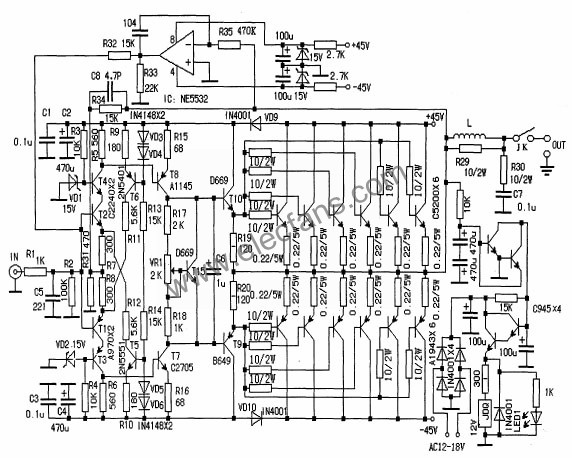
The circuit schematic diagram is shown in the accompanying drawings (only one channel is drawn in the power amplifier part in the figure, and the other channel is the same).
Circuit characteristics
1. This power amplifier refers to the current negative feedback circuit of the Japanese Golden Voice (most of the Japanese Golden Voice power amplifiers use current negative feedback circuits). The current negative feedback amplifier can well take into account the two indicators of nonlinear distortion and transient intermodulation distortion, and the conversion rate is more than the voltage The negative feedback amplifier is good and can provide the ideal amplification effect.
2. The power amplifier adopts a fully symmetrical circuit, a complementary push-pull amplification form, and the input stage uses a constant current source as the load, which effectively isolates the power supply noise and reduces nonlinear distortion, so that the power amplifier noise is extremely low, and the background is competing. Strong analytical power.
3. The power amplifier circuit is simple, pure DC line, frequency bandwidth, small transient distortion, fast response. The dynamic range is wide, and the DC servo circuit is adopted, and the output is automatically adjusted to zero.
4. The audio amplifier circuit of this power amplifier adopts high-frequency, low-noise and frequency-specific name tubes, which improves the signal-to-noise ratio and conversion rate.
5. The final stage current amplifier uses 6 pairs of Toshiba high-power famous tubes for Class A parallel output per channel. The 6 tubes are connected in parallel to improve the damping coefficient and enhance the driving ability of the circuit. It can easily drive large speakers with low impedance.
6. This power amplifier carefully sets the input and output ground wires, with the horn protection part, but without the rectifier filter part and the radiator, just find the large power amplifier cabinet with exposed radiator on both sides and install it. Because the heating temperature of the pure Class A amplifier is very high, it is not suitable to be close to the filter capacitor. It is recommended to use 4 to 8 10000uF / 50V Japanese famous brand electrolytic capacitors for the rectifier filter. The rectifier bridge is above 30A. It is best to use a 400W ~ 32V toroidal transformer for each channel And the rectifier filter part, the effect is better.
Component selection and debugging
1. The circuit board adopts epoxy glass fiber board, and all circuits are silver-plated.
2. The resistors are all made of metal film resistors (1 / 2W American DALE resistors are used for the audio part, and the ceramic resistors for the final power tube emitter resistors). The capacitors are made of high-quality brands such as Japan's Black Diamond / ELNA / Ruby.
3. The amplifier should emit beautiful sound. In addition to using excellent lines. High-quality components must also be selected. The tubes at all levels are strictly matched. The tubes at the input level use Japan ’s Toshiba pair tube A970 / C2240. The sound is warm and soft. The T5 and T6 use 2N5551 / 2N5401. The voltage amplification stages T7 and T8 use the Toshiba fever famous tube A1145 / C2705, the driving level adopts Hitachi medium power pair B649 / D669, the final power output tube requires Fr ≥ 30MHz, Vceo ≥ 160V, PCM ≥ 150W, this power amplifier uses Japanese Toshiba tube A1943 / C5200 (must be original, the original tube is the same Good performance, long life, especially suitable for use in pure class A power amplifier), the constant voltage tube uses Hitachi D669, and it is fixed on the same radiator with the power tube. The tubes of the above audio amplification channels should be strictly matched, and the error of the β value of the two tubes should be less than 3%. As long as the matching is strict, the midpoint potential should be below tens of millivolts.
4. Under the condition of installation and checking without error, adjust VR1 to the minimum value without connecting the sound source and speaker, disconnect the power tube emitter resistance, turn on the power, pay attention to observe whether there are abnormal phenomena, such as component heating, smoke, etc. If there is any abnormality, you should power off the inspection, find out the problem and then proceed to the next debugging.
5. Connect back to the emitter resistance of the power tube and check the power. No problem to measure the midpoint voltage (if the transistors are strictly matched and the DC servo circuit is normal, the midpoint voltage should be below tens of millivolts), measure the voltage of 0.22Ω / 5W, slowly adjust VR1, so that the voltage across the terminal is 33mY, at this time The static current of the final stage is about 900mA (that is, 150mA per tube), the midpoint potential is unchanged, and the measurement is continued for 15 to 30 minutes. The final static current of the machine is about 2.5A (420mA per tube) for a period of time. According to the pure class A power calculation formula P = 2I2R, it is calculated that the power amplifier has 100W pure class A power on an 8Ω load, and the power amplifier has a 360W output power per channel on an 8Ω load.
The author uses Marantz CD as the sound source. The speakers use Hivi R1C + SS6N self-made bookshelf monitor speakers. It shows excellent music positioning and resolution. The low frequency control is very good (freely retractable). Overall, it has a rich sense of hierarchy and high frequency. Slender, mellow and beautiful, especially when playing a genuine Hugo CD, the singer's tooth sound and the breath of breath are clear and audible. Fully reflects the advantages of pure Class A amplifiers.
Tin Zinc Alloy Wire is a kind of electronic welding material speciallized for metal spraying of the end face of metalized film capacitor.The capacitors have been widely used in high-speed rail,automobiles,new energy and aerospace fields.
Application Fields: Metal spraying material is a kind of electronic welding material specialized for metal spraying of the end face of metalized film capacitor.
Tin Zinc Alloy Wire
Tin Zinc Alloy Wire,Zinc Alloy Wire,Tin Zinc Alloy Soldering Wire,Alloy Wire
Shaoxing Tianlong Tin Materials Co.,Ltd. , https://www.tianlongspray.com