1 Introduction
The use of a bus-type data transmission scheme in the new missile guidance and control system is to solve the current missile flight control system. The structure is complicated, the reliability is low, and the electromagnetic compatibility of the system is caused by the transmission of analog signals through point-to-point directly connected cable networks. A good way to deal with many ills such as resistance to damage. The electro-hydraulic servo mechanism is an important part of the missile control system. Its performance often seriously affects the control accuracy of the missile and even determines the success or failure of the flight. In the bus-type missile control system, the missile electro-hydraulic servo mechanism will be connected to the bus as a node on the bus, so an interface must be designed to connect the bus to the electro-hydraulic servo mechanism. The structure of the missile bus control system is shown in Figure 1.
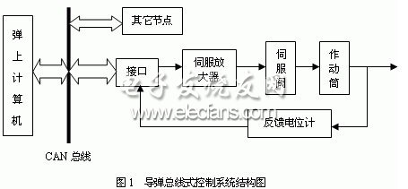
In the missile flight, the inertial sensitive element obtains the missile flight parameters, and then sends them to the computer on the missile. After the computer calculation, the control instructions are formed. To control the missile's flight trajectory.
1.1 CAN bus
CAN (Controller Area Network) is the controller area network. CAN bus is a multi-master local network, which can effectively support the communication function of distributed control system or real-time control system; it uses two-wire serial communication to work. The microprocessor can be hung on the CAN bus through the CAN controller. It has a strong error detection function as well as priority and arbitration functions. It can be used in a high-noise environment with a transmission rate of up to 1Mb / s.
1.2 PC / 104
PC / 104 is the mechanical electrical standard for industrial embedded PCs. Its formulation provides a standard system platform for embedded applications. The PC / 104 bus is fully compatible with the PC / AT bus (ISA). It complies with the IEEE-P996 standard, and all signal levels are compatible with TTL. The PC / 104 module generally provides a 6mA bus drive capability and can drive 15 low-power TTL loads. Compared with ordinary industrial control machines, PC / 104 bus has the following characteristics:
â‘ The PC / 104 module is fully compatible with PC software and hardware. You can use the existing richer and mature hardware, software development tools and methods, design knowledge and other resources, with a short development cycle and low cost.
â‘¡ The PC / 104 module has a small size, low power consumption, no heat dissipation, can be stacked, and has system-level performance and chip-level size.
â‘¢ A unique combination of vertical stacking or lateral plugging is adopted between the modules. After the modules are stacked, there are pillars and screws for fixing at the four corners. The reliability is high, the configuration is flexible and convenient, and it is convenient for troubleshooting and repair.
â‘£ The peripheral modules are complete, and users can select various functional modules to design special systems to meet different needs.
⑤ Wide operating temperature range, generally 0-70 degrees.
â‘¥ Most modules use a single + 5V power supply, reducing the power requirements of the system.
2 Interface hardware design
According to the requirements of the actual system, the function of this interface is mainly to realize the communication with the on-board computer, as a terminal in the control system to receive the commands and data from the on-board computer, to perform the calculation and execution of the control algorithm A / D conversion, and transmit the motion information and status data of the servo mechanism to the computer.
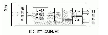
The transmission medium between the interface and the CAN bus uses shielded twisted pair, and the interface hardware uses modules based on the PC / 104 bus standard, mainly including: D / A and A / D modules, processor modules, external storage modules, and bidirectional driving in time Sequence control module, CAN bus communication module. as shown in picture 2.
1) D / A module
In this design, we choose the AD7547 digital-to-analog converter of American AD company. It is a dual 12-bit current output DACS (data collection and control system) with the following characteristics: wide operating voltage (12-15V); good resistance to power supply voltage interference; compact package (24 feet 0.3 inches) DIP package); low gain error. It can be used with most microprocessors and is compatible with TTL and CMOS levels. Through independent reference voltage and feedback resistance, it can also provide four-quadrant multiplier function. Its internal mainly includes three parts: control logic circuit, A-channel digital-analog conversion circuit and B-channel digital-analog conversion circuit. The logic control circuit selects the corresponding analog-to-digital converter through three simple control signals: CSA, CSB and WR, and latches the data to be converted at the same time. The basic control principle of the A-channel digital-to-analog conversion circuit is: through the CSA and WR control signals, the 12-bit conversion data is latched into the data register of the A-channel conversion circuit at a time, and the A-channel conversion circuit starts digital-analog conversion to convert After the analog output. The control principle of the B-channel conversion circuit is similar to the A-channel.
2) A / D module
The A / D module converts the feedback signal output from the displacement detection device of the missile electro-hydraulic servo mechanism into a digital quantity for the computer to process. The control accuracy of the system largely depends on the accuracy of the detection feedback device. According to the feedback parameters of the servo mechanism and the requirements of the system performance indicators, the AD674A analog-to-digital conversion chip produced by the American AD company is used in this design. It is a 12-bit successive approximation type fast A / D converter with a maximum conversion speed of 15 microseconds. The AD674A is equipped with a tri-state output buffer circuit, so it can be directly connected to various typical 8-bit or 16-bit processors without additional logic interface circuits, and is compatible with CMOS and TTL levels.
3) Processor module
In this design, the processor uses a PC / 104 embedded computer. Because it has a fast calculation speed, it mainly provides high-speed data calculation and processing functions for the interface. These data include the control data sent by the computer on the bus and The output of the displacement detection device collected by the analog-to-digital conversion module is processed and integrated by the processor to form an output to control the action of the actuating cylinder.
4) Two-way drive and timing control module
The address bus and data bus of the CAN controller SJA1000 are designed according to INTEL's 8-bit microcontroller bus specifications, and cannot be directly connected to the PC / 104 bus. The two bus signals are switched through a bidirectional bus drive circuit and a timing conversion circuit in the middle. That is, the data bus and I / O address bus of the PC / 104 bus become the data / address multiplexing bus of the SJA1000 after the bus driver and timing conversion. There is a key timing switching problem here. The signals of the control bus must also undergo corresponding conversion to drive the bus controller SJA1000. The block diagram of the conversion circuit is shown in Figure 3.
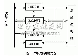
In FIG. 3, the thin solid line indicates the data line and the address line, the thick solid line indicates the control line, and the thin dotted line indicates the chip select signal.
In this design, the data bus and the address bus are connected to the data and address multiplexing bus of the CAN controller SJA1000 through two eight-bus receiver-transmitter 74HC245. 74HC245 is an 8-bit bus receiver transmitter with a three-state output, which can carry out bidirectional data transmission. In the middle, a programmable logic chip GAL16V8 was used to design a timing control logic circuit to control the work of two 74HC245s, perform timing switching, and avoid possible conflicts between data and addresses. The chip select signal is generated by a piece of 74H688, which is an 8-bit numeric comparator / equivalence detector. Set the I / O address through the band switch, use 74HC688 to compare whether the address information on the PC / 104 bus and the set I / O address are the same, and if they are the same, a chip select signal is generated for the SJA1000. The signal switching of the control bus is also realized by the programmable logic chip GAL16V8.
5) Communication module
CAN bus communication module is composed of CAN controller SJA1000, photoelectric isolator 6N137, CAN transceiver 82C250, as shown in Figure 4.
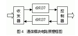
a) SJA1000 is a standard CAN bus controller produced by PHILIP Company. It is fully compatible with the basic CAN bus controller PCA82C200 in hardware and software design. It has fully compatible pins and protocol CAN2.0A, which can be replaced. In addition, it also supports the CAN2.0B bus expansion protocol set. It has two working modes: basic mode and extended mode. In basic mode, it has 32 working registers, while in extended mode, it has 127 working registers. This design selects the basic working mode, which supports CAN2.0A protocol. On the one hand, the CAN controller has the function of interface with the microcontroller, on the other hand, it can also complete all the functions required by the CAN communication protocol.
b) 82C250 is a CAN bus transceiver, which is the interface between the controller and the physical bus. The transmitting and receiving ends of the CAN controller are not allowed to be directly connected to the bus. The reason is that when a node in the network is not powered or fails, it will affect the normal operation of the entire network. In addition, if there is a short circuit fault on the bus, the output driver of the CAN controller may be damaged. Therefore, an interface circuit must be provided between the CAN controller and the bus in the implementation application. 82C250 can provide differential transmission capability to the bus and differential reception capability to the CAN controller. 82C250 also has strong driving ability, can increase the communication distance (up to 10Km), can perform slope control to reduce radio frequency interference, and has instant anti-interference ability. It has three working modes: high-speed mode, slope control mode and standby mode. In this design, the slope control mode is adopted, and the slope on the bus is controlled by connecting an 18-ohm resistor to the 8-pin.
c) 6N137 is a high-speed photoelectric isolator produced by TI. It has a high speed and can meet the requirements of the system. After the photoelectric isolation circuit is used, the bus driver and the bus controller are powered separately, which cut off the electrical connection between the two. Further improve the anti-interference performance.
SK6812 Digital LED Strip is one of single signal transmission full color led strip.
SK6812 is an intelligent internal control LED light source and each component is a pixel point.
Have same functions and same PCB With WS2812B, but difference is the SK6812IC can be inside and outside,Working Voltage is 5-24VDC. The Sk6812IC can be replace the WS2812B in some cases.
SK6812 Digital LED Strip
RGB CCT LED Strip,SK6812 LED Strip,SK6812 Digital LED Strip,Mini RGB LED Strip
SHEN ZHEN SEL LIGHTING CO.,LTD , https://www.sel-lighting.com