220V AC power through the capacitor C1, R1 step-down current limit after the AC voltage at A and B points is about 15V, rectified by VD1 ~ VD4. Get DC voltage of about 14V on C2 as high-brightness LED VD5 ~ VD8 The working voltage of the LED is about 14mA. Since the capacitor C1 does not consume active power, the power consumed by the bleeder resistor is negligible, so the power consumption of the entire circuit is about 15 & TImes; 0.014 ≈ 0-2 (W).
This corridor light made of high-brightness LEDs turns off during the day and automatically lights up after dark. The annual electricity consumption does not exceed 2 degrees and the service life can reach 10 years.
Circuit working principle
The circuit of the LED corridor light is shown below. The circuit is composed of a capacitor step-down circuit, a rectifier circuit, an LED lighting circuit, and a photoelectric control circuit.
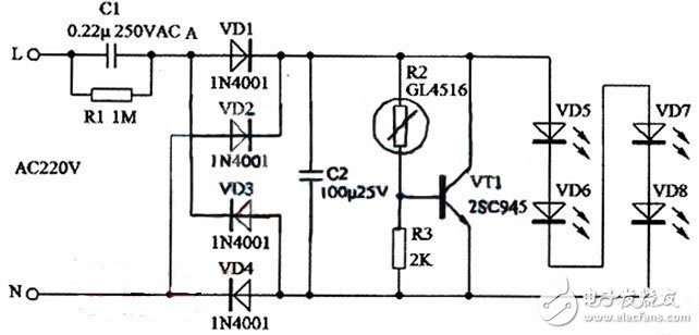
220V AC power through the capacitor C1, R1 step-down current limit after the AC voltage at A and B points is about 15V, rectified by VD1 ~ VD4. Get DC voltage of about 14V on C2 as high-brightness LED VD5 ~ VD8 The working voltage of the LED is about 14mA. Since the capacitor C1 does not consume active power, the power consumed by the bleeder resistor is negligible, so the power consumption of the entire circuit is about 15 & TImes; 0.014 ≈ 0-2 (W).
In order to further save power and extend the service life of high-brightness LEDs, a photoelectric control circuit consisting of a photoresistor R2, a resistor R3 and a triode VT1 is added to the circuit. At night, the resistance of the photoresistor R2 can reach 100K or more. The voltage across C2 is divided by R2 and R3, and the DC bias voltage supplied to the base of VT1 is very small. VT1 is cut off, which has no effect on the operation of the LED. During the daytime, due to the effect of photoelectric effect, the resistance of R2 can be Reduce to below 1OK, when VT1 is turned on and close to saturation, since the current through C1 can only reach 15mA at maximum, the voltage on C2 can drop below 4V due to the shunt of VTl.
Because the operating voltage of each LED should reach 3V or above to start working, the four series should reach 12V or more, so the LED can not normally emit light.
Then, after the VT1 shunt "short circuit", why does the power consumption of the circuit become smaller? This is because the capacitor step-down circuit can basically be regarded as a constant current source when the output voltage is not too high, and its power consumption is proportional to the load resistance. After the VT1 shunt reduces the voltage on C2, it is equivalent to the load. The resistance is reduced, so the power consumption is reduced. Taking the AC voltage across A and B down to 5V as an example, assuming that the AC current passing through C2 reaches 15mA, the power consumption of the circuit is about 5 & TImes; 0.015 ≈ 0.08 (W). Therefore, for an average of 12 hours per night, for example, the electricity consumption for one year is: (0.2 & TImes; 12 + 0.08 × 12) × 365 ≈ 1.2 (kWh), that is, 1.2 kWh.
Component selection and installation
In the figure, C1 uses a 0.22μ 250VAC metallized polyester film capacitor. R2 uses CDS photoresistor, model GL4516, its bright resistance (10Lux) is 5~1OKΩ, dark resistance is 0.6MΩ, other types of CDS photoresistor can also be used. When the parameters are different, just adjust the resistance of R3 properly. can. VD5~VD8 use high-brightness white light-emitting diodes with a rated operating current of 20mA.
The corridor lights can be retrofitted using old energy-saving lamps. The original lamp tube is removed, and the remaining hole is just used as the exit hole of the light-emitting diode. Since the hole is relatively large, four small holes can be opened as the substrate at the position corresponding to the light-emitting diode by the cardboard. Do not re-create the circuit board during assembly, use the original circuit board to assemble, leave 4 rectifier diodes, remove the original 400V electrolytic capacitor and replace it with 100 μ 25V electrolytic capacitor, remove the redundant components on the circuit board, The other components on the corridor light are lap welded using the original solder joints. A hole is formed in the upper part of the circular outer casing as a light-transmitting hole of the photoresistor, so that external light is irradiated on the photoresistor.
After installation, turn on the power. Under normal light in the room, if the light-transmitting hole light blocking the photoresistor is lit, the light will be turned off after the light is turned off, indicating that the working state of the light is normal. Finally, install the lamp in the corridor used. If the light is on when the daytime light is slightly dark, increase the resistance of R3. Conversely, if the light is not dark at night, the light can not be lit properly. Reduce the resistance of R3. Under normal circumstances, no debugging is required. The corridor light after lighting.
To increase battery voltage and capacity of a power system, cells have to be connected in series or in parallels. Due to unequal self-discharge and physical variations of the cells as different as it was made in factory, the State-Of-Charge(SOC) of the cells will differ sooner or later in the following no matter whether it been used or not. Therefore, the discharge process has to be stopped when one cell has reached its minimum voltage and the energy in the other cells is waste. The utilizable energy of a series circuit is limited by the weakest cell in the pack. To completely discharge all cells, weaker cells must be recharged. This process is called cell balancing or cell equalizing, which is much more energy-efficient than any other methods. And it is very important for prolonging battery lifespan due to reducing internal resistance and slowly sulfided.
Our Battery Equalizer is designed specially for Electric Vehicle Power, which it packed in series by 12V cells. The equalizer with smaller smart pulse is installed onto battery bank in everyday's driving. Keeping all the batteries in your electric vehicles equalized allows them to be completely charged and to give off a completely discharged. And make to give you a longer travelling distance and better experience. By adding our smart pulse equalizer to your vehicle power battery bank, the cell batteries are desulfated and equalized on a consistent basis so they will always be in as new ones. When there is no internal resistance in the cell batteries, there is less wear and tear when vehicles starting and being speed up. The total electrical power system benefits as the batteries are equal as in like new conditions.
Smart pulse Equalizing system for 48, 60, 72-Volt battery banks, patented pulse technology reduces and prevents sulfation buildup. Maximizes the performance of all lead-acid battery including VRLA, AGM, GEL and Flooded cell batteries.
Electric Vehicle Battery Equalizer
Electric Vehicle Battery Equalizer,Battery Equalizer,Power Battery Equalizer,Tricycle Smart Battery Equalizer
Shenzhen Daceen Technology Co., Ltd. , https://www.daceen-sz.com