Impedance matching The internal resistance of the signal source is equal to the characteristic impedance of the connected transmission line and the phase is the same, or the characteristic impedance of the transmission line is equal to the magnitude of the connected load impedance and the phase is the same, respectively called the input end or the output end of the transmission line. Impedance matching state, referred to as impedance matching. Otherwise, it is called impedance mismatch. Sometimes it's called a match or a mismatch.
Impedance matching is a suitable way to match a signal source or transmission line to a load. Impedance matching is divided into two cases of low frequency and high frequency. We start by driving a load from a DC voltage source. Since the actual voltage source always has internal resistance, we can combine an actual voltage source into an ideal voltage source in series with a resistor r. Assuming that the load resistance is R, the power supply electromotive force is U, and the internal resistance is r, then we can calculate the current flowing through the resistance R as: I=U/(R+r). It can be seen that the smaller the load resistance R is, then The larger the output current. The voltage on the load R is: Uo = IR = U / [1 + (r / R)], it can be seen that the larger the load resistance R, the higher the output voltage Uo. Then calculate the power consumed by the resistor R as:
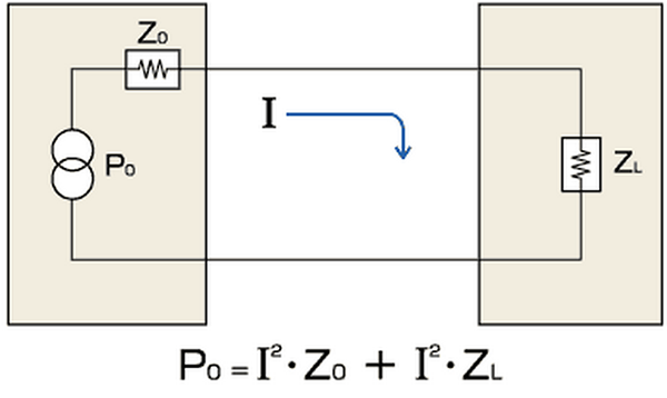
P=I2&TImes;R=[U/(R+r)]2&TImes;R=U2&TImes;R/(R2+2&TImes;R×r+r2)
=U2×R/[(Rr)2+4×R×r]
=U2/{[(Rr)2/R]+4×r}
For a given source, the internal resistance r is fixed, and the load resistance R is chosen by us. Note that in [(Rr)2/R], when R=r, [(Rr)2/R] can obtain the minimum value of 0, at which time the maximum output power Pmax=U2/(4× can be obtained on the load resistor R r). That is, when the load resistance is equal to the internal resistance of the signal source, the load can obtain the maximum output power, which is one of the impedance matching we often say. This conclusion also applies to low frequency circuits and high frequency circuits. When the AC circuit contains capacitive or inductive impedance, the conclusion is changed, that is, the signal source and the real part of the load impedance are required to be equal, and the imaginary parts are opposite to each other. This is called conjugate matching. In the low-frequency circuit, we generally do not consider the matching problem of the transmission line, only consider the situation between the signal source and the load, because the wavelength of the low-frequency signal is very long relative to the transmission line, the transmission line can be regarded as a "short line", and the reflection can be Consider (it can be understood as this: because the line is short, even if it is reflected back, it is the same as the original signal). From the above analysis, we can conclude that if we need a large output current, we choose a small load R; if we need a large output voltage, we choose a large load R; if we need the maximum output power, we choose the internal resistance of the source. Matched resistor R. Sometimes the impedance mismatch has another meaning. For example, some instrument outputs are designed under specific load conditions. If the load conditions change, the original performance may not be achieved. In this case, we will also call impedance mismatch. .
In high-frequency circuits, we must also consider the problem of reflection. When the frequency of the signal is high, the wavelength of the signal is very short. When the wavelength is short compared with the length of the transmission line, superimposing the reflected signal on the original signal will change the shape of the original signal. If the characteristic impedance of the transmission line is not equal to the load impedance (ie, it does not match), a reflection will occur at the load end. Why the reflection and the characteristic impedance are solved when the impedance is not matched, which involves solving the second-order partial differential equation. We will not elaborate here. For those interested, please refer to the transmission line theory in the books on electromagnetic fields and microwaves. The characteristic impedance of the transmission line (also called the characteristic impedance) is determined by the structure and material of the transmission line, and is independent of the length of the transmission line, as well as the amplitude and frequency of the signal.
For example, a commonly used CCTV coaxial cable has a characteristic impedance of 75 Ω, while some RF devices typically use a coaxial cable with a characteristic impedance of 50 Ω. Another common transmission line is a flat parallel line with a characteristic impedance of 300 Ω, which is common on TV antenna frames used in rural areas and is used as a feeder for Yagi antennas. Because the input impedance of the TV's RF input is 75Ω, the 300Ω feeder will not match. How to solve this problem in practice? I don't know if you noticed that there is a 300Ω to 75Ω impedance converter in the accessory of the TV (a plastic package, the one with a round plug on one end, about two thumbs) . It is actually a transmission line transformer that converts the 300Ω impedance to 75Ω so that it can be matched. It should be emphasized here that the characteristic impedance is not a concept with the resistance we usually understand. It is independent of the length of the transmission line and cannot be measured by using an ohmmeter. In order not to produce reflection, the load impedance and the characteristic impedance of the transmission line should be equal. This is the impedance matching of the transmission line. What are the adverse consequences if the impedance is not matched? If it does not match, it will form a reflection, energy transfer will not pass, reduce efficiency; will form a standing wave on the transmission line (simple understanding, that is, some places have strong signals, some places have weak signals), resulting in a decrease in the effective power capacity of the transmission line; It can't be fired or even damage the launching equipment. If the high-speed signal line on the board does not match the load impedance, oscillation, radiation interference, etc. may occur.
When the impedances don't match, what are the ways to match it? First, consider using a transformer for impedance conversion, as in the example in the TV set above. Second, consider using series/parallel capacitors or inductors, which are often used when debugging RF circuits. Third, consider the use of series/parallel resistors. Some drivers have lower impedance and can be connected in series with a suitable resistor to match the transmission line, such as high-speed signal lines, sometimes in series with a resistor of tens of ohms. Some receivers have higher input impedances, and can use parallel resistors to match the transmission line. For example, a 485 bus receiver often has a 120 ohm matching resistor in parallel with the data line terminal. (starting series matching, terminal parallel matching)
To help you understand the reflection problem when the impedance is not matched, let me give two examples: Suppose you are practicing boxing - playing sandbags. If it is a sandbag with the right weight and the right hardness, you will feel comfortable when you hit it. However, if one day I put the sandbags on my hands and feet, for example, if I replaced them with iron sand, you still use the previous force to hit them, your hands may not be able to stand it - this is the case of heavy load, will Produces a great rebound. On the contrary, if I change the inside to something that is very light and light, if you punch out, you may be emptied, and your hand may not be able to stand it - this is a situation where the load is too light.
Solar Light is also known as a solar lamp or solar lantern is a lighting system composed of a LED lamp, polycrystalline solar panels, battery, charge controller and they may also be an inverter. Solar light fixtures are built to last with durable, waterproof, and weather-resistant constructions. Solar-powered outdoor lighting easy installation. Don`t need cables. Throughout the day the solar panels will cover the solar energy from the sun into electricity which will charge the battery. The intelligent solar controller charges the battery throughout the day and control to ensure that the battery is not overcharged. Solar led lights are great for illuminating areas without electricity such as gardens, parks, courtyards, streets, walkways, campuses, and so on.
Solar Light
Solar Led Motion Light,Solar Motion Sensor Light,Solar Motion Security Light,All In One Led Solar Street Light
Jiangmen City Pengjiang District Qihui Lighting Electrical Appliances Co., Ltd , https://www.qihuilights.com