Currently, electric vehicles (EVs) and plug-in hybrid vehicles (PHEVs) are highly regarded by consumers in more and more countries. In the United States, only one state in California has set a goal: by 2025, the number of electric vehicles will reach 1.5 million. Globally, the sales volume of electric vehicles and plug-in hybrid vehicles may be higher. By 2020, Europe is expected to reach 3 million units. The targets set by relevant Chinese government departments will further exceed the above-mentioned areas. By 2020, it is expected. The number of plug-in hybrid vehicles is expected to reach 5 million. In this context, the demand for electric vehicle charging stations will naturally rise sharply.
This article refers to the address: http://
The biggest factor affecting consumer confidence in electric vehicles is that users are concerned about whether EV/PHEV can travel for a long time due to the small number of charging stations. A sufficient number of ready-to-use charging stations can help alleviate this concern and further increase the penetration of electric vehicles. Today, there are some free charging stations in office buildings, parking lots, restaurants and shopping centers, but consumers are increasingly demanding “paid charging†stations, and more will be needed in such systems. Technology and communication. As a result, the technical requirements for these systems will undoubtedly continue to increase, and system developers face the dual challenge of keeping the device small and simple while also achieving increased functionality.
Wireless charging and communication
At present, the charging stations in many urban areas look and work like parking meters, but there is an additional charging cable for users to plug into the car. There are three common types of charging stations (or levels):
* Class 1 and Class 2 charging stations are "metering-capable" AC power supplies that utilize the EV's built-in charging function circuit.
* The Level 3 charging station contains the DC "Quick Charger". These chargers bypass the automotive power factor correction (PFC) circuit and feed 400 VDC to the battery charging stage.
Although the functional level and power are different, the three are the same: measure the power consumption and provide the charging function. In the "paid charging" station, you must also communicate with the back-end network for credit card charges, mobile user mobile phone package deductions, and even cash transactions. This feature requires a flexible architecture for the system.
What does this mean for the technology used? Near Field Communication (NFC), which is essential for mobile payments, is an ultra-short-range communication standard that works very close to RFID. Each smartphone or NFC-enabled device has a unique verification code associated with a payment account. Ethernet, Power Line Communications (PLC) and Wi-Fi are required for payment processing as well as advanced metering and other control functions. In addition, you need to communicate with the vehicle you are charging. Most electric vehicles need to communicate with the charging station via CAN, RS232, Ethernet, PLC or with pulse width modulation (PWM) signal transmission. So, how can the designers of these paid charging stations meet all the necessary requirements in such systems while keeping the design relatively simple and cost-effective?
An easy solution to this challenge is to use an embedded controller or processor that provides NFC, PLC, Wi-Fi, CAN, and 10/100 Ethernet communications in a single device with management metering , housekeeping and power level control. This allows developers to keep the space and bill of materials costs on the printed circuit board to a minimum while integrating all critical communications and advanced protection features into the system. A dual-core microcontroller based on the C2000 C28x + ARM Cortex-M3 from TI is an example of such an integrated embedded processor. In addition to the necessary measurement, communication, and interface requirements, these MCUs can handle power stage control.
The analog interface and processing power of the embedded controller is the basis of the metering system. By using this analog-integrated device, designers can easily monitor the voltage and current required for single-phase and three-phase AC measurements and monitor output levels in higher DC-based output systems.
Decomposition design requirements
We will divide the system into two parts to simplify the given diagram:
1. The power source being monitored
2. Low voltage communication side of the system
Since we are dealing with both low voltage and high voltage systems, the isolation requirements between high voltage and low voltage systems must also be considered. As mentioned earlier, EV chargers are currently divided into three categories: Level 1 and Level 2 (AC charging) and Level 3 (DC Fast Charging). In Level 1 and Level 2 systems, the charging station architecture appears to be very similar to the standard metering applications common in most smart grid applications, as shown in Figure 1. The meter is directly connected across the single-phase or three-phase AC power supply (public grid) and there is no power control level inside the system. It operates in much the same way as a residential meter, monitors the power flow through the system, and increases communication with the vehicle and payment gateway that is charging. In addition, such systems may also have safety monitoring and disconnection capabilities.
Both the Class 1 and Class 2 chargers utilize the vehicle's built-in charging system, which includes a power factor correction boost stage and a high voltage DC charging circuit. The Class 1 charger is based on a standard 120/240 VAC level and provides up to 16 A of charging current. Level 2 charging can use 240 VAC or 480V three-phase AC, but is limited to 32A. Moreover, in a Class 1 or Class 2 charging scenario, the charger acts only as a metering interface between the utility grid and the vehicle being charged, and there is no energy conversion stage.
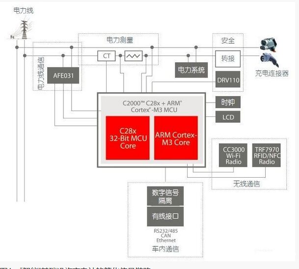
Figure 1: Simplified signal link for a "smart" infrastructure charging station
The DC Fast Charge System works in a very different way, converting the AC supply voltage level to a boost DC level that can deliver up to 400A. A Level 1 or 2 charger can charge a normal EV in 4 to 8 hours, while a DC boost charger can provide the same level of charging in as little as 20 to 30 minutes. Although the power levels of Level 1 and Level 2 charging are completely different compared to Class 3 charging, these three levels of charger metering applications are common because the metering input is always AC power and is located before any PFC circuit level.
In any charging class charging charger application, we have the following requirements (or potential requirements, depending on billing and communication options):
* The measurement of the actual electricity consumption of the vehicle being charged (usually in kWh);
* Fault management and system protection;
* Payment processing (credit card, smart card, bill collection or mobile phone payment via NFC using cellular phone);
* Receiving processing communication (Wi-Fi, Ethernet or PLC);
* Charge management communication to the vehicle (via CAN, RS232, Ethernet, power line communication or PWM signal transmission).
The metering system can be easily partitioned to incorporate all of the above functions into a single embedded processor with a dual core processor and a subsystem. In addition, many chip vendors offer a variety of solutions for radio communication and system level isolation. The system can be divided into smaller sub-segments according to the above functions, starting with the measurement and determination requirements of the kilowatt-hour (kWh) billing bills to be issued to the customer.
As shown in Figure 2, the metering stage utilizes an analog system for a dual-core device and utilizes the internal ADC and processing power of a CPU (in this case, the C28x DSP core) that is paired with a current transformer. To enhance tamper resistance, a shunt resistor circuit may be required. When used in conjunction with a real-time clock, the process for measuring kWh becomes a standard voltage and current measurement, depending on whether the current transformer and shunt resistor are used in parallel and the total number of phases determines up to 7 C2000 MCUs. The combination of analog to digital converter inputs can be easily handled.
Cable Joint Kit,Jointing Kit,Waterproof Cable Joint,Underground Cable Joint
Changshu Herun Import & Export Co.,Ltd , https://www.herunchina.com