1. DMA Access Memory Performance
The EDMA3 architecture offers a wide range of features to enable efficient and parallel data transfers. This section explores the various factors that influence its performance, including memory type, address offset, and more.
1.1 DMA Transfer Overhead
The general transmission delay is defined as the time between the moment the EDMA is triggered and the start of the actual data transfer. Since measuring the exact start of data transmission can be complex, we use the completion time of the smallest data unit to estimate the overhead. This value may vary depending on the source and destination addresses used. Table 4 shows the average clock cycles measured from the EDMA Trigger (Write ESR) for a minimum data transfer (1 word) to the EDMA transfer end (read IPR=1), as tested on a 1GHz C6678 EVM with 64-bit DDR at 1333MTS.
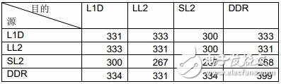
Table 4: EDMA CC0 Transmission Overhead

Table 5: Additional Costs for EDMA CC1 and CC2 Transmissions
EDMA CC0 is connected to an internal bus switching network closer to SL2 and DDR, resulting in lower overhead when accessing these memory types. In contrast, EDMA CC1 and CC2 are linked to a bus network near L1 and LL2 of the DSP core, which gives them lower overhead when accessing those memories. IDMA is typically used for copying data within LL2, and the average overhead for the tested IDMA was 61 clock cycles.
For small data transfers, the overhead of the DMA becomes a critical factor. The time it takes to transfer a single data unit is almost entirely determined by this overhead. Therefore, when dealing with small data copies, it's essential to weigh the trade-off between using the DMA and using the DSP core directly.
1.2 Differences Between EDMA Transmission Engines
The C6678 includes 10 EDMA3 Transfer Controllers (TCs). These controllers are not all the same. Table 6 outlines their differences.
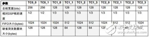
Table 6: Differences Between EDMA Transfer Engines
Table 7 compares the maximum throughput of each EDMA TC on a 1GHz C6678 EVM (64-bit DDR at 1333MTS). The test parameters were ACNT=1024, BCNT=128, and AB_Sync (ACNT x BCNT transferred at once).
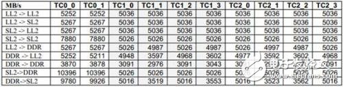
Table 7: EDMA TC Throughput Comparison on 1GHz C6678
When transferring data between SL2 and DDR, TC0_0 and TC0_1 achieve twice the throughput of other TCs. Unless otherwise stated, the EDMA performance data in this document is based on TC0_0.
1.3 EDMA Bandwidth and Transmission Flexibility Trade-offs
EDMA3 supports a variety of flexible transmission configurations. While it can take full advantage of memory bandwidth in most cases, certain configurations might lead to reduced performance. To design an efficient system, it's important to understand which configurations offer optimal performance and sometimes make trade-offs between flexibility and efficiency.
1.3.1 Consideration of First Dimensional Size (ACNT) – Burst Block Size
To maximize the bandwidth of the transmission engine, it's crucial to transfer as large a block of data as possible.
To fully utilize the 128-bit or 256-bit bus, ACNT should be an integer multiple of 16 bytes. For optimal EDMA bursts, ACNT needs to be a multiple of 64 bytes. And to make the best use of the EDMA FIFO, ACNT should be at least 512 bytes.
Figure 7 shows the measured throughput when transferring 1 to 24K bytes of data from SL2 to DDR on a 1GHz C6678 EVM (64-bit DDR at 1333MTS).
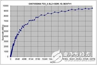
Figure 7: Effect of ACNT on EDMA Efficiency
As shown in the test results, the larger the ACNT, the higher the bandwidth utilization.
1.3.2 Two-Dimensional Transmission Considerations – Transmission Optimization
If a 2D transmission (AB_Sync) is linear (BIDX = ACNT) and ACNT is a power of two, EDMA will optimize this to a 1D transmission. We tested various combinations of ACNT and BCNT on a 1GHz C6678 EVM (64-bit DDR at 1333MTS). Figure 8 presents the results for linear 2D transmission, showing that the bandwidth is determined by the product of ACNT x BCNT, regardless of BCNT.
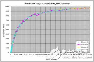
Figure 8: Linear 2D Transmission
If the 2D transmission is not linear, the bandwidth utilization depends entirely on ACNT (as seen in Figure 7).
On And Off Grid Solar Energy System
Benefits
1. Energy Efficiency: Off grid and on grid solar system incorporates batteries, which can store excess energy generated during peak sunlight hours for use when solar energy is insufficient.
2. Cost-Effectiveness: While the initial installation cost might be higher than a simple Solar Panel setup, This system can lead to long-term savings by potentially reducing the need for grid power and lowering overall energy costs.
3. Environmental Benefits: By using renewable energy sources, this solar electric system significantly reduce carbon emissions and contribute to a cleaner environment.
4. Grid Support: In some cases, on and off grid solar system can also support the main power grid, helping to stabilize it and improve its efficiency.
In summary, a off grid and on grid solar system represents an innovative approach to harnessing clean energy, offering a robust solution that maximizes the benefits of multiple renewable resources while ensuring a stable and sustainable energy supply.
On And Off Grid Solar System,Off Grid And On Grid Solar System,Off Grid And On Grid Solar,Off Grid On Grid Solar
Ningbo Taiye Technology Co., Ltd. , https://www.tysolarpower.com