RFID system antenna design
RFID (Radio Frequency. IdenTIficaTIon, radio frequency identification technology) is a kind of automatic identification technology. It uses wireless radio frequency to carry out non-contact two-way data communication to identify the target and obtain relevant data. Its core components are the reader and the electronic tag. Through the radio waves emitted by the reader within a distance of several centimeters to several meters, the information stored in the electronic tag can be read to identify the identity of the items, people and appliances represented by the electronic tag . RFID technology has been widely used at home and abroad, and has been used in public transportation, subway, campus, social security and other fields. This article mainly summarizes and studies the more practical methods in the design of RFID reader antennas through the comparison of various RFID reader systems in practical work.
1 Actual RFID antenna design mainly considers physical parameters
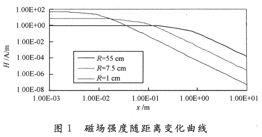
1.1 Magnetic field strength Moving electric charge or current will generate a magnetic field, and the magnitude of the magnetic field is expressed by the magnetic field strength. The working distance of the RFID antenna is closely related to the strength of the magnetic field generated by the antenna coil current.
The magnetic field strength of the circular coil (under the premise that the near-field coupling is effective, the judgment of whether the near-field coupling is effective is in section 1.3) can be calculated using equation (1): 
Where: H is the magnetic field strength; I is the current strength; N is the number of turns; R is the antenna radius; x is the effective distance.
For a rectangular conductor loop with side length ab, the magnetic field strength curve at distance x can be calculated using the following formula.

The results confirm that the distance from the antenna coil is very small (x
1.2 The best antenna diameter When the distance x from the transmitting antenna is constant and the current I in the transmitting antenna coil is simply assumed to be constant, if the radius R of the transmitting antenna is changed, the distance x and the antenna radius R can be used The relationship between them gives the maximum magnetic field strength H. This means that for each RFID reader's range, there is an optimal antenna radius R. If the selected antenna radius is too large, the magnetic field strength is very small at the distance x = 0 from the transmitting antenna; on the contrary, if the antenna radius is selected too small, then its magnetic field strength is attenuated by the ratio of the third power of z ,as shown in picture 2.
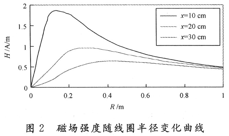
Different readers have different operating distances and different optimal antenna radii, which corresponds to the maximum value of the magnetic field strength curve.
Mathematically speaking, that is, derivation of R, as shown in equation (3):

Calculated from the zero point of the formula is the inflection point and the maximum value of the function. 
The optimal radius of the transmitting antenna corresponds to the value of 2 of the maximum expected reader. The negative sign of the second zero point indicates that the magnetic field strength of the conducting circuit propagates in both directions of the x-axis. It should be pointed out here that the prerequisite for using this formula is that the near-field coupling is effective. The following introduces the concept of near-field coupling.
1.3 Near-field coupling When the formula mentioned above is actually used, the effective boundary conditions are:
d <R and x <λ / 2π, the reason is that when the above range is exceeded, the near-field coupling loses its effect and begins to transition to a long-distance electromagnetic field. The initial magnetic field on a conductor loop starts from the antenna. During the transmission of the magnetic field, an electric field is also formed due to the increase in induction. In this way, the most primitive pure magnetic field is continuously converted into an electromagnetic field. When the distance is greater than λ / 2π, the electromagnetic field finally gets rid of the antenna and enters the space as an electromagnetic wave. The range before the electromagnetic wave enters the space is called the near field of the antenna. The design of the RFID antenna involved in this article is based on the concept of near field coupling. Therefore, the distance should be limited to the above range.
1.4 Tuning The RFID system reader can be equivalent to an RLC series circuit, where R is the resistance of the winding coil and L is the inductance of the antenna itself. In the general tuning process, since the capacitance of the antenna coil itself has little effect on resonance, it can be ignored. Therefore, in order to obtain the maximum current of the antenna coil at the operating frequency of the reader, an additional capacitor C is needed to complete the tuning of the antenna. Achieve this goal. The relationship between the tuning capacitor, the inductance of the antenna and the operating frequency can be obtained by the following Thomson formula, namely: 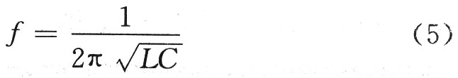
1.5 Estimation of inductance The physical meaning of the inductance value is: the ratio of the magnetic flux generated in the total area surrounded by the current to the current strength surrounded by the conductor loop. When the actual RFID antenna is debugged, the inductance value of the reader antenna can be measured by an impedance analyzer. In the case of limited conditions, an estimation formula is often used for estimation. Assuming that the ratio of the diameter d of the conductor to the diameter D of the conductor loop is small (d / D <0.001), the inductance of the conductor loop can be simply approximated as: 
In the formula: N is the number of turns of the wire-wound antenna; R is the radius of the antenna coil; d is the inner diameter of the conductor; μ0 is the permeability of free space.
The number of coil turns is estimated by the following approximate formula. In practical applications, the two formulas can be used for comparison: 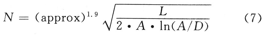
In the formula: L is the coil inductance, the unit is nH; A is the antenna coil surrounding area, the unit is cm2; D is the wire diameter, the unit is cm.
1.6 Quality factor of the antenna The performance of the antenna is also related to its quality factor. Q affects both energy transmission efficiency and frequency selectivity. Although an excessively high Q value can increase the output energy of the antenna, at the same time, the passband characteristics of the reader will also be affected. Therefore, when actually adjusting the Q value, a compromise must be considered. The Q value is adjusted by connecting a resistor R1 in series with the RLC equivalent circuit. The specific formula is as follows:
Q = ωL ï¼ (R + R1) (8)
2 Actual debugging The design of the RFID antenna needs to consider many factors. The above are important physical parameters in the actual debugging process. After the above physical parameters are clarified, after the RFID system requirements such as the desired distance and operating frequency are given, under the condition of limited conditions, a simple RFID antenna design can be carried out as needed. The following gives a practical example of RFID antenna design applied to rail transit. Here, a coiled antenna with a maximum expected working distance of 1 cm and an operating frequency of 125 kHz is designed. The system requires that the radius of the reader antenna coil be as small as possible, not exceeding 1 cm. Specific steps are as follows:
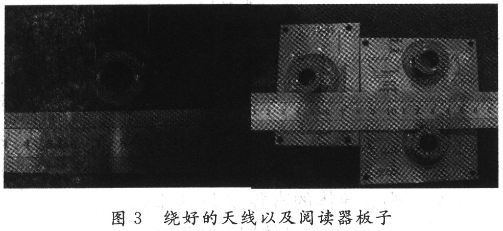
First determine the optimal radius of the antenna, which should not be too large or too small. The ideal optimal antenna radius should be twice the expected working distance. In actual design, a compromise should be considered in the design according to the design requirements. Under the premise of ensuring the system requirements, it is as close as possible to the optimal value. In this example, the optimal radius of the reader antenna should be 1.4 cm, but considering that the system requires that the radius of the antenna does not exceed 1 cm, in practice, the radius is 0.8 cm. Under the allowable conditions, in order to make the effect better, you can add an antenna skeleton with appropriate amount of ferrite, antenna and reader board, as shown in Figure 3.
Secondly, according to the operating frequency and the requirements of the system itself to determine the approximate range of inductance, the inductance in this system is 600 ~ 800μH. Furthermore, the empirical formula of the relationship between the inductance and the number of turns is used to roughly estimate the number of turns of the winding. In this example, take an inductance of 700μH and wind the antenna with a copper wire with a diameter of 0.27 mm. By formula ![]() Calculate the number of turns is about 266 turns, after winding, according to Thomson's formula
Calculate the number of turns is about 266 turns, after winding, according to Thomson's formula ![]() Select the tuning capacitor used. Measure the resonance frequency with related instruments (such as a spectrum analyzer and a vector network analyzer). At this time, because the inductance is only estimated, and the matching capacitor selected has a certain nominal value, it cannot be consistent with the calculation. So there will always be errors.
Select the tuning capacitor used. Measure the resonance frequency with related instruments (such as a spectrum analyzer and a vector network analyzer). At this time, because the inductance is only estimated, and the matching capacitor selected has a certain nominal value, it cannot be consistent with the calculation. So there will always be errors.
Since the tuned capacitance is known and has a fixed nominal value, it can be inferred from the frequency measured at this time according to the Thomson formula to infer the size of the inductance required when this frequency is just reached, that is, the winding coil inductance . Looking at the frequency deviation, gradually increase or decrease the number of coil turns according to the inductance estimation formula until it reaches the specified resonance frequency of 125 kHz. The actual pictures of measuring the resonance frequency with a vector network analyzer and a spectrum analyzer are shown in Fig. 4 and Fig. 5.
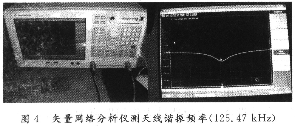

3 Conclusion According to the display of the vector network analyzer and the spectrum analyzer, this RFID antenna has successfully resonated at 125 kHz. Next, you can calculate the size of the resistor used to adjust the Q value according to the mentioned formula, and then conduct further joint debugging test according to the requirements of the system. In actual engineering, RFID readers and tags have various circuit structures, but in the final analysis, they are all equivalent to RLC resonant circuits. For example, the antenna design of PHILIPS MIFARE series readers, so this article is for various RFID systems. Antenna design has universal guiding significance.
Galvanized Monopole tower
Galvanized monopole Towers are used for a variety of communication applications and are ideal for use when zoning is difficult. Monopoles can also be designed as camouflage poles: pine tree poles, flag poles, palm poles and other stealth towers. Many uses include cellular monopoles, wireless internet monopoles, wifi tower, homeland security monopoles, two-way monopoles, and wind tower monopoles.
1. Based on its shapes, it is generally divided into 5 types: Goblet type, cathead type, cathead type, shaped type and barrel type.
Based on application, it can be divided into: Strain tower, straight line tower, angle tower, transposition tower (tower for transposition of wire phase position), terminal tower and crossing tower, etc.
2. Their structural features are: All kinds of towers are of space truss structures; Bard are mainly composed of single equal angle steel or assembling angle steel; Materials are generally Q235(A3F) and Q345(16Mn); Bars are connected by black bolts with shearing force; Entire tower is composed of angle steels, link plates and bolts; A few components like tower base are assemblies of welded steel plates for convenience of hot galvanizing anti-corrosion, transportation and erection.
3. For steel towers that with height below 60m, shackles are mounted on one of main columns for construction people to climb to work. Our Company is a large scale enterprise specializing in manufacturing of 220KV (330KV) electric power steel tower with advanced manufacturing facility and international top-ranking assembly line.
Monopole Tower, Telecommunications Monopole, Steel Monopole Tower, Monopole Transmission Tower,Galvanized Monopole
YIXING FUTAO METAL STRUCTURAL UNIT CO.,LTD( YIXING HONGSHENGYUAN ELECTRIC POWER FACILITIES CO.,LTD.) , http://www.chinasteelpole.com