Abstract: The radio frequency identification system using TMS3705 as the radio frequency base station is introduced. The working principle, hardware composition, software design method and software flow of its application in automotive anti-theft devices are given. The specific algorithm of 16-bit cyclic redundancy check used in TMS3705 information reading.
Radio frequency identification (Radio Frequency IdenTIficaTIon, hereinafter referred to as RFID) technology is a new technology developed in recent years, it is a product of the organic combination of radio frequency technology and IC card technology. Compared with ordinary magnetic cards and IC cards, RFID technology has the advantages of easy use, fast data exchange speed, easy maintenance and long service life. In particular, it solves the two major problems of passive (no power in the card) and contact-free. Unlike contact recognition technologies such as magnetic cards and IC cards, the recognition function can be completed without physical contact between the transponder and reader of the RFID system, so multi-target recognition and moving target recognition can be realized, so it can be applied to a wider range occasion. The radio frequency identification system and the corresponding data verification algorithm introduced in this article are a successful attempt to apply radio frequency identification technology in car alarms.
1 Basic principles of RFID
A typical radio frequency identification system is composed of a transponder (transponder), a reader (reader), and a data exchange and management system. The basic working principle of the system is: the reader reading and writing terminal continuously sends out a set of electromagnetic signals with a fixed frequency (generally 134.2 kHz). In this way, when an LC in a non-contact card (transponder) chip resonates in series When the circuit enters the working area of ​​the reader terminal, and its working frequency is the same as the frequency of the signal sent by the reader terminal, under the excitation of electromagnetic waves, the LC resonant circuit resonates. Resonance charges the capacitor in the card. At this time, a unidirectional electronic pump connected to the other end of the capacitor can send the charge in the capacitor to another capacitor and store it. When the voltage value of the accumulated charge reaches 2V, this voltage can be used as the working power supply of the transponder. At this time, the transponder responds to the reader's request, and modulates the information and sends it out at the same time for the reader to demodulate and read. The E2PROM in the transponder is used to store the ID number (64-bit code length) of its unique electronic tag and other user data.
figure 1
2. Radio frequency identification car anti-theft alarm design
The RFID system developed in this paper is based on Texas Instruments' TMS 3705 as a radio frequency signal reading and writing chip, and the company's RI-TRP-RR2B (read-only type) as a transponder. The communication between the base station chip and the microprocessor (MCU) in this design requires only two general I / O lines, so it is very convenient to use. The modulation and demodulation circuit is shown in Figure 1.
The signal transmitted by the transponder is received by the reader antenna and processed by the base station and then sent to the I / O port of the microprocessor. What is sent to the reader is the FSK (Freqney Schiff Key) signal. The reader is only responsible for the demodulation of the signal, and the decoding of the signal is done by the microprocessor. The microprocessor can perform decoding operations according to the high and low duration of the input signal.
2.1 Data storage format in the RI-TRP-RR2B radio frequency card
There are a total of 14 bytes of data in the RI-TRP-RR2B transponder, and their storage order is as listed in Table 1. The user data area has a total of 10 bytes, of which the 2nd to 9th bytes are the user's 64-bit ID area, and the 10th and 11th bytes are the CRC check code.
Table 1 Data in RI-TRP-RR2B
| 1st byte | Start byte FEH |
| 2nd to 11th byte | User data area |
| 12th byte | Stop byte FEH |
| 13th and 14th bytes | 13th byte = 2nd byte; 14th byte = 3 bytes |
2.2 Car anti-theft device based on radio frequency identification technology
The system takes AT89C51 single-chip microcomputer of ATMEL as the core, and its hardware composition is shown in Figure 2. The system consists of radio frequency identification device, external memory, voice circuit, 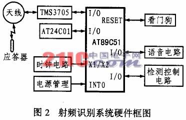 Clock circuit, power management circuit, watchdog and detection control circuit. This system has high compatibility and can be used with other anti-theft devices. It is a cost-effective car anti-theft device. The main features of the anti-theft alarm system are as follows:
(1) The ordinary car anti-theft device mainly uses the keyboard input method to identify the driver's identity. This method brings a lot of inconvenience to driving, and because of its limited password combination, it is easier to be stolen and deciphered. The use of radio frequency identification technology to identify identities can effectively solve this problem. The owner only needs to carry the transponder (32mm) close to the reader's induction coil (entering the induction range of about 7cm), and the identity recognition can be completed in an instant, and its password should not be deciphered, thus greatly improving the anti-theft effect. If the original transponder is lost, the user only needs to press the "learn" button, and then close the spare transponder to the induction antenna to complete the ID learning, the original ID will be automatically cleared, and the lost response The transponder fails, and the standby transponder takes effect.
(2) Its external memory adopts AT24C01 series E2PROM of ATEL. AT24C01 is a 1k-bit electrically erasable memory with I2C bus, which can be used to store the owner's ID and the logo information of the single-chip microcomputer before power failure. Since it is a non-volatile memory, the information stored in it will not be lost after power-off. After re-powering on, the system will return to the state before power-off, which can effectively prevent man-made damage to the car's power supply and improve safety.
(3) The voice circuit is based on the ISD1420 integrated voice chip, which can realize the recording and playback of multiple voices by combining conditioning and power amplifier circuits, and its sound quality is good. The circuit can easily realize the security prompt and alarm function of the anti-theft system.
(4) The power management circuit and the watchdog circuit are completed using MAX705. The chip has both power management and watchdog functions. Among them, the combination of power management and single-chip software can be used for data protection for sudden power failure, so that the single-chip computer can save the state information immediately before power failure to E2PROM for reading when it is powered on again. The watchdog circuit can effectively monitor the single-chip microcomputer to prevent various interference on the car to make the single-chip microcomputer into an endless loop, thereby improving the stability and reliability of the whole machine.
image 3
(5) The detection control circuit is used to detect various status information of the car for the purpose of decision-making and judgment by the single-chip microcomputer. Including the detection of the door, the detection of the power supply, the detection of the brake signal and the detection of the button. The control circuit includes direction light control, power supply control, central lock control and hub lock control.
3 Software design of RFID system
The core of the software design of the radio frequency identification system is to read and verify the signals sent by the radio frequency card. The flow chart of the identification subroutine is shown in Figure 3. The radio frequency card used in this system is a read-only card, so only its 64-bit ID needs to be read out, and then after verification and comparison with the existing ID in E2PROM, the identity of the owner can be determined. 
3.1 Reading of RF signals
Figure 4 shows the format of each byte of the signal, which consists of 10 bits. The first bit is the start bit, fixed at 1, the last bit is the stop bit, fixed at 0, the 2nd to 9th bits are the actual transmitted data (the first bit received is LSB), because it is negative logic? The data needs to be processed in reverse.
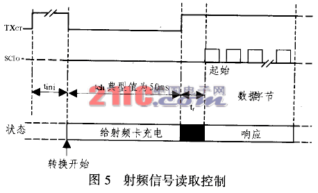
Figure 5 shows the timing of the reader reading data. The data sent by the radio frequency card adopts FSK modulation. During operation, set TXCT to 0, delay 50ms, and then restore TXCT to 1. After about 3ms, SCIO began to output data. The first byte of this data is the starting byte, and a total of 14 bytes of data are output.
3.2 CRC data check algorithm
The CRC check is set to check whether the information field is transmitted correctly. It is a function of the information field. In this paper, 16-bit cyclic redundancy check code (CRC-CCITT) is used, and the polynomial generated is:
![]()
The CRC check code is widely used in communication because of its simple implementation and high accuracy. The CRC-CCITT used in this paper can detect all double errors, odd bit errors, burst errors with a burst length of not more than 16, 99.97% burst length with a burst error of 17 and 99.98% burst. Burst errors with a transmission length greater than or equal to 18 The operation of the CRC check code can be implemented with a shift register and a half adder? The specific check principle is shown in Figure 6. The verification process at the sending end is as follows:
(1) First set the initial value of the CRC check code (2 bytes) to 00H and 00H (0 to 15 in Fig. 6 indicate CRC bits 0 to 15).
(2) The CRC check codes are all shifted to the right by one bit, and XOR is performed at A with the first bit of the data to be CRC checked.
(3) After the operation in step 2, if the result at A is 1, then reverse the MSB (bit 15), and then check whether the MSB is 1, if the MSB is 1, then reverse the phase 13 and bit 10, otherwise go to step 4. If the result at A is 0, check whether the MSB is 1, if the MSB is 1, then reverse phase 3 and bit 10, if not, go to step 4.
(4) Check whether the calculation has been performed 64 times at A. If not, repeat steps 2 to 4. 
(5) Repeat steps 2 to 4 to do CRC operation. The final value obtained is the CRC check code.
The process of verification at the receiving end is actually all information codes plus CRC check code, and then as a whole to find the process of CRC check again, if the final result is all zero, it means that the CRC check is correct, otherwise it means an error .
The transponder information must be read in strict accordance with its timing, otherwise the correct information required will not be obtained. Due to space limitations, this article does not list specific procedures.
4 Conclusion
This article mainly introduces the method and implementation of radio frequency identification technology applied to automobile anti-theft system. The new car anti-theft device developed by the author using radio frequency identification technology has been tested and tried several times, and its performance is not only stable, but also safe and reliable. Good results have also been achieved in practical applications. Practice shows that the anti-theft device has the advantages of advanced technology, practicality, convenience, good compatibility, small size and full functions. It is an ideal car anti-theft system.
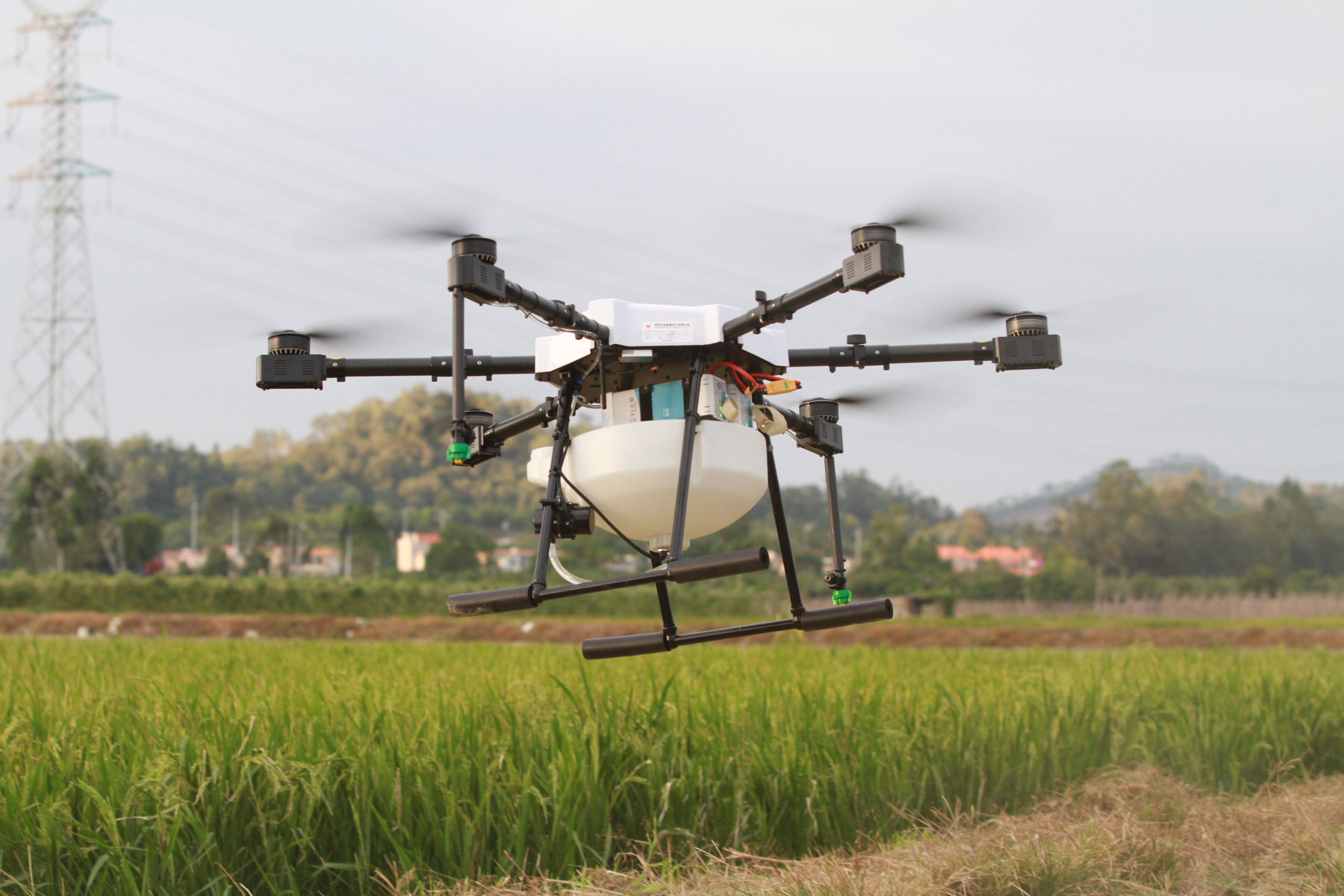
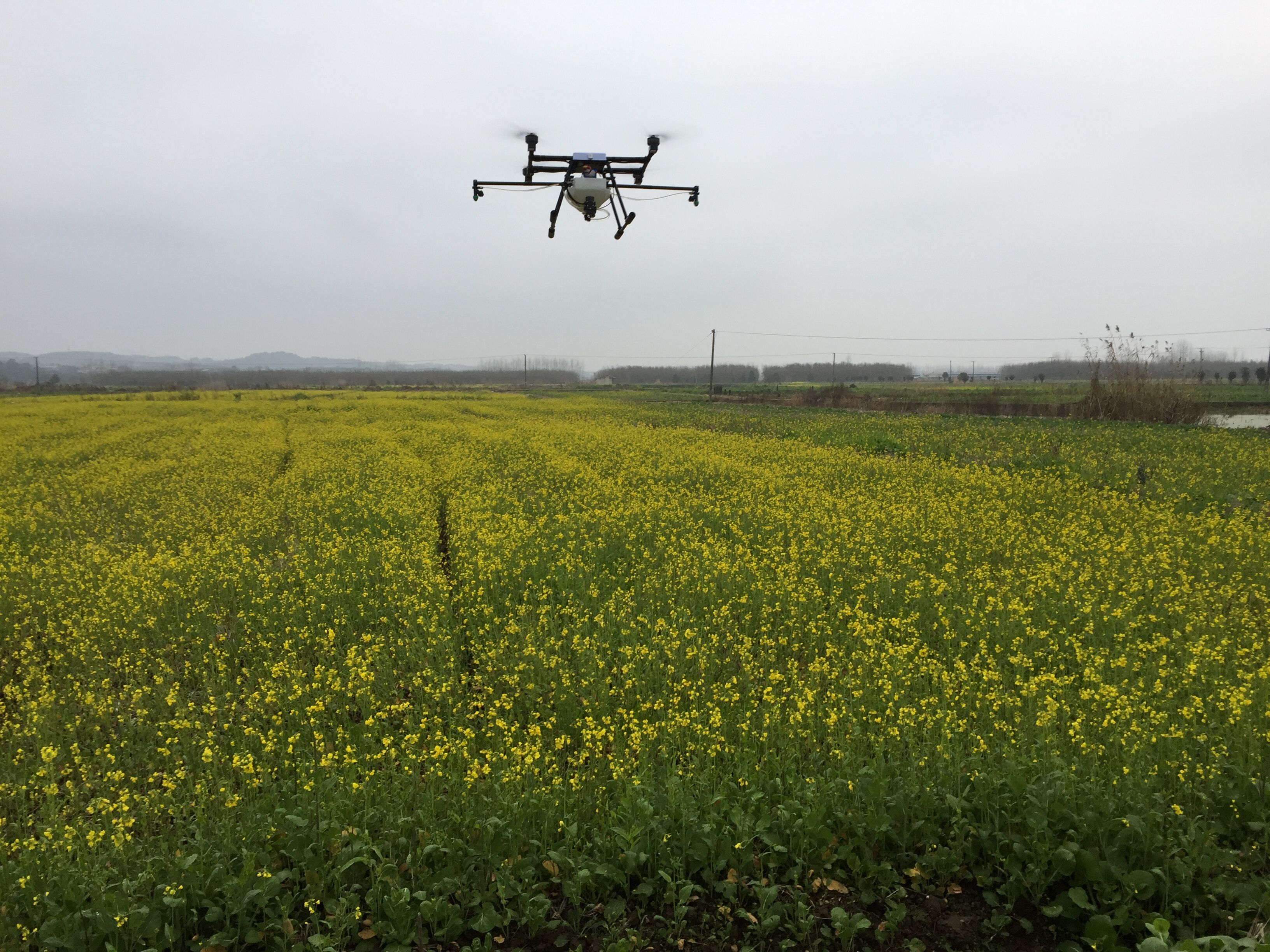
Agriculture Drone Include the Agricultural Spraying Drones , Agricultural Crop Analysis Drone, Mist Sprayer Drone, Fertilizer Spreading Drone ,Tichogramma Dropper Drone etc. Use the Agricultural Drone can stop crop diseases with higher efficiency than the traditional method. For a farmer,Agriculture Drones is a Tool ,The Most important is they need a reliable drone can work continuouse, And lower cost of the spare parts, Easily maintenance, Thoese is what we did.
A stronger frame with light weight like a foundation of a building. We use carbon fiber and Aluminium Alloy made our Drone Frame , from the farmers spraying work experiences to improve the stable structures. And improve the Drone Motors and Drone Propellers to get more thurst and lower current for longer flight time.

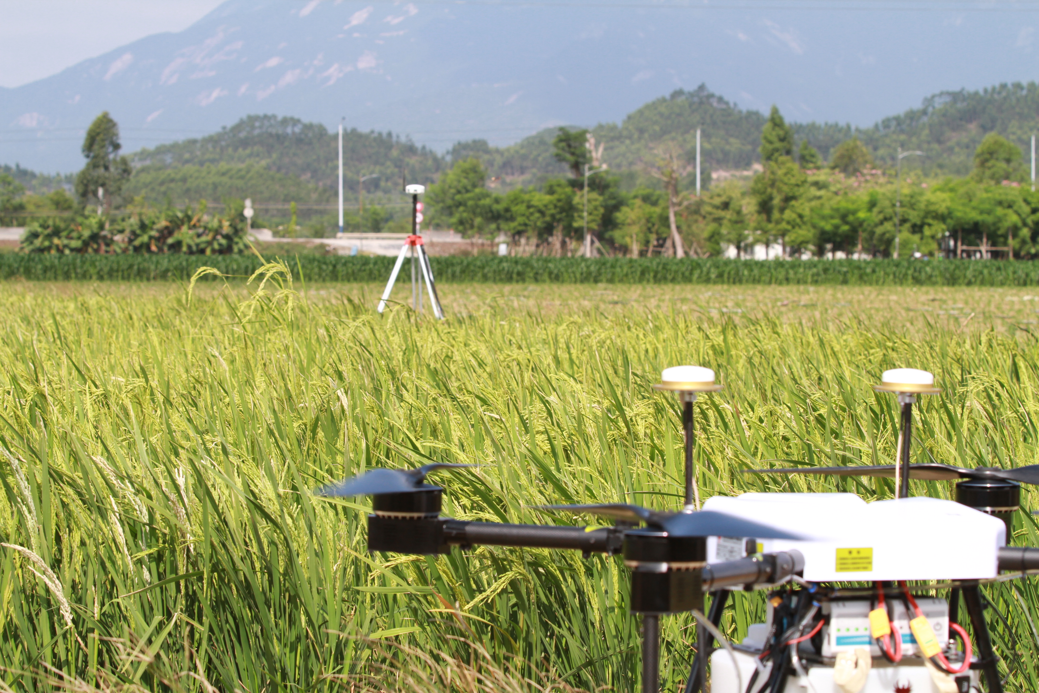
Agriculture Drone
Drone Farming,Crop Spraying Drone,Agriculture Drone Spraying,Use Of Drones In Agriculture
shenzhen GC Electronics Co.,Ltd. , https://www.jmrdrone.com