Design of Controller for Electric Wheel Dump Truck Based on DSP
1 Introduction
Heavy-duty electric wheel dump truck is an efficient transportation equipment for large open-pit mines and water conservancy projects. At present, there are about 600 heavy-duty electric wheel dump trucks in operation in China's metallurgy, coal industry and large-scale water conservancy construction projects. Domestic companies that use electric drive control systems have always relied on the import of Statex from the General Electric Company (GE) Series MCU control system. Due to the large number of plug-in boards in the system, the circuit is complicated and debugging is difficult. In addition, the working environment of the electric wheels is poor, which makes this type of car have high failure rates, troublesome maintenance, and expensive spare parts. In the past, there were some technical researchers in factories, mines and research institutes who analyzed and reformed these products [1,2], but they did not fundamentally solve the problem. To this end, Hunan University and Xiangtan Electric Co., Ltd. jointly developed a 154T electric wheel dump truck microcomputer control and fault diagnosis system. The on-board electronic control subsystem of this system is developed with DSP as the core processor. The original single-chip control system is updated and upgraded, and is compatible with the original system to develop products with independent intellectual property rights.
2. DSP-based controller hardware design
The vehicle-mounted control system works in the environment of -30 ° C ~ 40 ° C, the control accuracy is ≤5%, the overshoot σ≤5%, the rise time tS≤3 s ~ 5s, and it is required to comply with the IE60077 traction power equipment regulations. It mainly completes the switch logic control of the motor, the automatic excitation adjustment of the generator and motor of the electric vehicle traction and braking process, and the real-time collection of fault signals.
According to the design requirements, the core CPU of the controller selects TMS320F2812 chip [3]. This chip is a high-performance fixed-point chip developed on the basis of F24X. The advanced internal and external structure makes the processor especially suitable for motors and other motion control applications, and can truly implement a single-chip controller. F2812 adopts 32bit operation and the main frequency of 150MHZ. It contains 16KRAM, 128KFLASH, 16-channel 12-bit high-speed A / D conversion, 16-channel PWM, 52-channel digital I / O, 4-channel timer and built-in WATCHDOG. And equipped with dedicated motor control peripherals (event management module EVA, EVB), can work in the environment of −40 ° C to 85 ° C. Using TMS320F2812 can realize all the functions of the controller without external bus expansion.
The hardware block diagram of the controller is shown in Figure 1. The input part of the controller has 3 pulse input modules, 34 switch quantities are sent to DSP after photoelectric isolation and level conversion, and 14 analog quantities are input after channel switching, amplification, filtering and fast A / D conversion. The output has 28-channel switch quantity and 2-channel PWM analog output module after photoelectric isolation and level conversion. The two synchronization signals of TPS1 and TPS2 are input to the synchronous trigger module to ensure the synchronous operation of the generator and the electric wheel. The controller is equipped with two RS485 serial communication ports, which can ensure reliable communication with the host computer (fault diagnosis machine). The controller also has a real-time calendar clock circuit and a 64Kx8-bit power-off retention accessor FM25L256, which can collect and save locomotive running real-time data and fault data in real time.
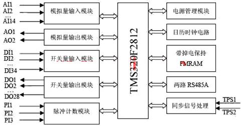
Figure 1 Controller hardware system block diagram
3. Design of the controller software
The control system software has functions such as communication, system management, control and information processing, and can realize the control requirements of the system. The main program of the system mainly includes system initialization, logic operation, traction / braking control and fault data analysis and processing. The main program flow chart is shown in 2. Due to the large number of peripherals in the system and the high real-time requirements, interruption methods are used for phase-shift triggering, serial communication, AD sampling and digital filtering, speed measurement, 0.5ms timing and historical data storage in the system, ensuring the protection of electric vehicles. real time monitoring. System software debugging is carried out under CCS2.0 environment. Except for individual initialization programs written in assembly language in the system, all other parts are written in standard C, which is conducive to software modification, maintenance, and upgrades [4]. The system program is burned in the Flash memory of F2812, and all interrupt programs are loaded into the RAM of F2812 when running. In this way, you can avoid frequently fetching instructions from the slow Flash and affect the running speed, and give full play to the performance of F2812.
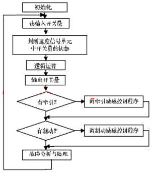
Figure 2 main program flow chart
In the above figure, the system initialization mainly completes the initialization of the entire system hardware and parameters. Including CPU work initialization, EV module initialization, interrupt vector and interrupt initialization, serial port initialization, fault diagnosis machine (PTU) setting parameter initialization and AD value and actual value proportional coefficient initialization. It also completes the setting of the scale factor of the feedback unit and the initial value of the input interface parameters of each function, the PI or PID regulator parameters, the turning point parameters of each characteristic curve and the scale (slope) coefficient. The logic operation is to use the switch input and related analog quantity to calculate the switch output and intermediate variables according to the 154T logic relationship provided by Xiangtan Motor Factory, and output all switch output. The vehicle speed and diesel engine speed signals sent by the sensor are processed by the EV module and output two PWM signals. The fault analysis and processing part mainly collects and saves fault data after the fault occurs and provides it to the host computer for analysis. The main program is as follows:
#include "Device.h" // DSP2812 HeadeRFile Include File
#include "Examples.h" // DSP2812 Examples Include File
#include "Global_Variables.h" // Global variables used in this project
#include "io.h"
#include "PulseIn.h"
extern void ReadDin (), OutDout (), LogicFuncTIon (), IniTIalFramAndCalendar ();
extern void WriteReadFramAndCalendar (Uint16 * BuffStartAddress, Uint16DataLength, Uint16 FramAndCalendarAddress, Uint16 OperateID);
void DigitalInFilter (); void Read_PIDPara_FromFRam ();
extern void Read_PIDPara (), ReadDin ();
Uint16 DI_Temp [5] [3], DI_Counter, i;
strRxBuf SciA_RxBuf, SciB_RxBuf; strTxBuf SciA_TxBuf, SciB_TxBuf;
Uint16 SCI_TImer; Uint16 RecFlag = "0xff"; Uint32 ii; Uint16 KPKI [9];
void main (void)
{
InitSystem (); InitSysCtrl ();
EINT; // Enable Global interrupt INTM
ERTM; // Enable Global realTIme interrupt DBGM
InitialFramAndCalendar (); InitPIDPara (); InitAllGlobalPara (); FaultInit (); // parameter initialization
CloseDo (DO_CNTRL);
// ... Init FRAM AND CALENDAR (omitted) //
for (;;)
{
if (Flag.bit.DI_FLAG == 1)
{GetInput (DI_Temp [DI_Counter ++]);
Flag.bit.DI_FLAG = 0;
}
if (DI_Counter> = 5) DI_Counter = 0;
DigitalInFilter (); // Read in and switch
VehicleSpeed_Switch (); // Output switching value according to vehicle speed
LogicFunction (); // Logical operation
OutDout (); // Switch output
OutPWM (); // Output PWM pulse
if (Flag.bit.AD_10MS == 1)
{Flag.bit.AD_10MS = 0; Renew_RTPara ();
RenewPidIn (); // Analog calculation, filtering, update PID_IN, curve calculation
}
if (Flag.bit.DIGITAL_200MS == 1)
{Flag.bit.DIGITAL_200MS = 0; PushRealTtimePara (); // Record real-time parameters
}
if (Flag.bit.DATE == 1)
{Flag.bit.DATE = 0; ReadDate ();
}
FaultMain ();
if (RecFlag == 1) {WriteReadFramAndCalendar (& (SciA_TxBuf.Data [2] .a), SciA_RxBuf.Data [2] .a, SciA_RxBuf.Data [1] .a, UpperComputerReadFramFlag); // Fault analysis and processing
for (ii = 0; ii <60000; ii ++);
}
else if (RecFlag == 0)
{SciA_TX_Ready ();
SciA_Start_Tx (); // Provide fault data, real-time data or other parameters to the host computer
RecFlag = 0xff;
}
} // end for
} // end main ()
The control of the electric wheel dump truck adopts PID adjustment mode, which is mainly completed by four subroutines of traction generator, brake generator, traction motor and brake motor. According to the speed V of the diesel engine measured by the speed sensor, calculate the given power E_Power of the generator. The left and right wheel speeds V_RIGHT and V_LEFT of the electric vehicle measured by the speed sensor calculate the output IF_V or braking current IM of the main rectifier cabinet. The program also determines whether the locomotive is overspeeding, and if overspeeding, the electric vehicle will automatically brake. From the diesel engine speed V and the feedback of the main rectifier cabinet output current IF, calculate the phase shifting trigger angle, thereby controlling the excitation current of the generator and the motor, so that the locomotive performance meets the traction curve, see Figure 3 (a). The phase shift trigger angle is calculated from the pedal potential signal, constant speed downhill signal, the left and right wheel speed of the electric vehicle, and the feedback braking current IM, thereby controlling the excitation current of the generator and the motor, so that the locomotive performance meets the braking curve , See Figure 3 (b).
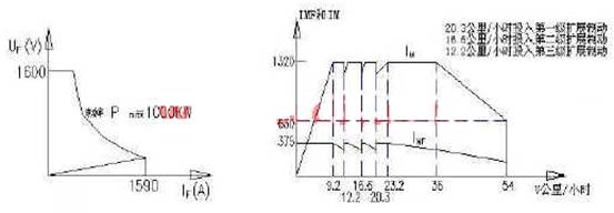
Figure 3 (a) Traction constant work curve (b) Braking curve
In the interrupt service program, the phase-shift trigger service program includes two parts: generator phase-shift trigger and motor phase-shift trigger, which are triggered by the edges (rising and falling edges) of the generator excitation circuit synchronization pulse TPS1 and the motor excitation circuit synchronization pulse TPS2, respectively. . After the trigger, after a delay t (calculated based on the conduction angle in the PID adjustment section), a trigger pulse with a width of 0.5 ms is issued. The serial communication service program is responsible for data communication between the lower computer and the upper computer, including PTU setting parameters, real-time data, fault data, and PID regulator parameters. The program design can refer to literature [5]. The AD sampling interrupt service routine is triggered by the peripherals of the AD module in the DSP, and the system starts sampling 14 channels (1 channel of standby) analog quantity. The sampled data is triggered by a 0.5ms timer interrupt program, and every 10ms performs weighted average filtering on 14 channels (each channel contains 8 sample values). The 0.5ms timer interrupt program provides a time reference for each PID regulator, digital filtering, serial communication, fault analysis, and 16-frame historical data storage.
4 Conclusion
The innovation of this article is: According to the user's design requirements, considering the special working environment of the electric wheel dump truck, the TMS32F2812 chip dedicated to digital control introduced by TI is used, and a circuit board is used to achieve at least 5 circuit boards of similar foreign products. All the functions that can be realized make the developed controller highly integrated, real-time and anti-interference ability, and adapt to the complex working environment of electric wheel dump trucks.
The controller designed in this paper can complete the switch logic control of the motor, the automatic excitation adjustment of the generator and motor of the electric vehicle traction and braking process, and the real-time collection of the fault signal. The prototype test shows that it has excellent performance and can be used to equip the new generation of domestic 108T, 154T and other series of electric wheel dump trucks can realize the localization of imported equipment spare parts.
The Rectifier Bridge is to seal the rectifier in a shell. Divided into full bridge and half bridge. The full bridge seals the four diodes of the connected bridge rectifier circuit. The half bridge is to seal together half of the four diode bridge rectifiers. Two bridges can be used to form a bridge rectifier circuit. One half bridge can also form a full-wave rectifier circuit with a center tap of the transformer. Rectifier circuit and operating voltage.
Rectifier Bridge
Diode Bridge Rectifier,3 Phase Bridge Rectifier,Rectifier Bridge,Rectifier Bridge
Dongguan Agertech Technology Co., Ltd. , https://www.agertechcomponents.com