Principle and Design of Calibration Control System for Water Flowmeter
Overview: The introduced water flowmeter verification control system can automate the calibration process and display the corresponding process flow screen. The system has an alarm prompt function for faults.
1 Introduction The past water flow meter verification system mainly uses manual and semi-manual methods for control. Its disadvantages are low verification accuracy, large flow fluctuations, small caliber range of verifiable meters, low automation, and low meter efficiency. In this paper, according to the technical requirements of the water flow meter verification, combined with the working status of the original verification system, and according to the design specifications of the automatic control system of the Ministry of Petroleum and Chemical Industry, a water flow meter verification control system is designed. The control system uses a computer and a frequency converter as the core to achieve true automatic control, which reduces the labor intensity of workers and improves labor efficiency. It can complete the entire series of water meter verification tasks, greatly saving verification costs and ensuring normal production operation. .
2 System composition The core of this system adopts the distributed control of upper and lower computers. The upper computer adopts Advantech high-quality IPC industrial-grade computer and is equipped with a 21 ″ large screen monitor. It mainly undertakes system management tasks, such as the detection of various data and signals. , Storage, analysis, calculation processing; display and reading of various process graphics, screens, and curves; viewing and monitoring of various events, fault alarms, records, and certificate checking and printing, etc. The lower-level computer adopts a programmable industrial controller produced by Japan OMRON company , The realization of all control tasks of the system, the execution of actions, and the output of the control mode are executed by the lower computer PLC. As the control center, it continuously exchanges various data and information with the upper computer at a very high frequency to realize the system control.
The entire verification system is divided into a system control part and an on-site inspection execution part, and the two parts are connected by a cable.
2.1 System control part The system control part is divided into five parts, as shown in Figure 1. (1) Central console of the entire system (system control cabinet)
It includes an Advantech IPC-586 industrial grade computer, a 21 ″ large screen monitor, a DPK-8400 receipt printer, a set of OMRON200H programmable logic controller PLC, 11 power distributors, 6 switching power supplies, 10 Air switch, 3 AC contactors, an alarm, a signal conversion processor, a set of four-way isolation relays, a frequency adjustment potentiometer and 30 buttons and indicator lights.
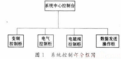
(2) The power supply and output signal wiring of the meter under test and the operation cabinet without data transmission of the meter. The cabinet is located at the verification site. It is equipped with a membrane operation panel, digital display tube, ready button and indicator light, emergency stop button, power switch, Pluggable control buttons and wiring cables.
(3) The solenoid valve cabinet is equipped with 8 solenoid valves and 4 relays, of which 4 solenoid valves respectively control the opening and closing of bottom valves on 4 standard tanks on site, and 2 solenoid valves control the commutation of two commutators . The six solenoid valves can be controlled automatically by the computer or manually by the buttons on the control cabinet. Each button is pasted with a label to avoid misoperation. The other two solenoid valves are reserved for use, and one controls the switch of the pneumatic drain valve on the DG200 pipeline. The 4 relays provide the upper computer with the switching status of 4 bottom valves.
(4) Inverter cabinet The cabinet consists of 175kW inverter, anti-interference reactor and intermediate relay, air switch, AC contactor and other electrical components. Its main function is to realize the frequency conversion start and stop of the motor. The start and stop of the inverter are divided into automatic and manual working modes: when the inverter works automatically, the upper computer automatically selects the motor to be started, and the lower computer sends the frequency control signal to the inverter according to the flow point set by the inspection timing ; When the inverter needs to be started manually, when the manual / automatic control button on the site is switched to manual mode, it can be achieved by adjusting the frequency adjustment potentiometer on the inverter cabinet, and manual frequency adjustment can be achieved through the conversion button on the system control cabinet Realize the remote operation of the site and the control room. At the same time, a liquid level relay for controlling the water tank of the vacuum pump is also installed in the frequency conversion cabinet.
(5) Electric control operation cabinet The operation cabinet is composed of four sides of the power distribution cabinet. Its main functions are to supply power to five motors in the pump room and to realize manual frequency conversion and power frequency start on its operation panel; / Automatic "switch, 15 start and stop pump buttons, 26 status indicator lights.
2.2 On-site inspection execution part The on-site inspection execution part is composed of a standard meter, a meter to be checked, a frequency converter, a standard tank, a commutator, and a pump set.
(1) Standard meters There are three standard gauges of DG300, DG200 and DG100 in the water flow verification system. The AC220V and DC5V working power of the standard meters are supplied by the system control cabinet. The pulse signal sent out when the standard table is working is collected into the upper computer through the PCL-836 acquisition card in the industrial control computer, and the flow rate is converted as the standard value through the calculation formula to verify the accuracy of the table under test.
(2) There are six types of calibrated meters from DG80 to DG300, and there are many types of power supply and signal output of the calibrated meter. The power supplies are: DC5V, DC12V, DC15V, DC24V, DC100V, AC110V, AC220V ; Signal output has two-wire system 4 ~ 20mA, four-wire system 4 ~ 20mA, 0 ~ 5V, 0 ~ 10V, 0 ~ 20mA. The power supply and signal input of the meter under test are selected by the lower computer. The output signal of the meter under test is converted into a level signal of 1 to 5V and 0 to 5V by a signal converter before entering the upper computer, and then converted into a flow rate by a PCL-818 acquisition card in the industrial control computer and displayed on the monitor.
(3) Inverter Inverter is the core of the execution part of the water flow verification system. The adjustment of the flow size and the stability of the flow are achieved by the upper computer through the inverter. The working state is extremely critical. Therefore, the upper computer Real-time monitoring of the inverter, you can directly see the working status of the inverter from the configuration screen. When the inverter fails due to some reason, the control system will issue an audible and visual alarm to remind the operator to deal with the failure, and the cause of the failure can be checked on the LCD screen of the inverter.
(4) There are four standard tanks in the standard tank and commutator system, and their volumes are 10m3, 2m3, 1m3, and 0.2m3. Each tank is equipped with a high-precision differential pressure transmitter to detect the inside of the tank. Liquid level. Among them, 1m3 and 0.2m3 tanks are No. 1 tank group, and 10m3 and 2m3 tanks are No. 2 tank group. Each of the two groups of tanks is equipped with a commutator. The commutator system consists of a solenoid valve, a cylinder, and a water separator , Photoelectric switch, shading board composed of five parts. The signal generated by the photoelectric switch is directly sent to the upper computer as the start and end of the verification timing.
(5) There are five pumps in the pump group, which are driven by 160kW, 90kW, 75kW, 30kW and 7.5kW motors. The flow rate of the pump is 0 ~ 1600m3 / h, 0 ~ 400m3 / h, 0 ~ 240m3 / h, 0 ~ 120m3 / h, 0 ~ 40m3 / h. When checking the meter, the upper computer selects and the lower computer executes different pumps according to the range of the tested table. The starting of the pump is divided into two working modes: frequency conversion starting and power frequency starting, both of which can be realized in the field and in the control room. In addition, a vacuum pump and a water tank are installed in the pump room. Its function is to start the vacuum pump to vacuum the pump body and the pipeline before starting the 160kW and 75kW pumps, so that the water fills the pump body.
3 System software design In order to enhance the flexibility of the system and ensure the normal operation of the system, the system is designed into two working modes: automatic control and manual control.
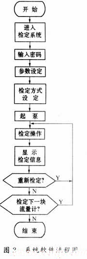
3.1 Automatic control mode First, power is supplied to the system through the key switch on the operation panel of the control room. At this time, the power indicators on the operation panel, the power supply cabinet of the on-site meter to be checked, and the frequency conversion cabinet are on, indicating that the system power supply is normal. Switch the “auto / manual†converter on the operation panel and the electrical control cabinet to the automatic working mode, then turn on the computer to enter the water flow verification system, first touch the ready button on the operation panel, wait for the ready indicator to light up in the parameter setting screen Setting parameters: select the calibration line according to the caliber of the meter to be tested; select the standard meter method, the standard tank method or the non-signal meter method according to the accuracy level or whether there is signal output; set the flow point and flow rate according to the range of the meter The setting of the point can be set automatically or manually; according to the working conditions of the table to be checked, select the power supply and signal reception type. After setting the above parameters and other items that need to be set, click "Start Verification" with the mouse. The system selects the pump according to the maximum range of the table to be checked. After the lower computer executes the start command, it automatically adjusts the working frequency of the inverter according to the different flow points, so that the pump works at the current flow point. At the same time, you can also select "Manual" after the "Frequency adjustment mode" option in the parameter setting screen according to your needs, then you can realize the flow rate adjustment through the frequency adjustment potentiometer on the operation panel. The control function also plays a monitoring role.
3.2 Manual control mode When selecting this working mode, you should first switch the “auto / manual†converter on the operation panel of the control room and the electrical control cabinet in the pump room to the manual working state, and the parameter settings are the same as above. Determine which pump to start according to the measured table range: First, close the output knob of the pump to be started on the electrical control cabinet, and jog the inverter start button on the frequency conversion cabinet. After the pump is started, you can adjust the operation panel or the electrical control cabinet. Potentiometer knob to adjust the flow. On-site and control room manual off-site operation of flow adjustment is achieved through the "control room frequency adjustment on-site" knob on the operation panel. The software flow chart is shown in Figure 2.
4 Conclusion This system has expanded its functions and expanded the scope of application of the system. Since it was put into operation, it has achieved satisfactory results due to its flexible configuration, good maneuverability, and stable work.
references
1 Sha Zhanyou. New practical digital measurement technology. Beijing: National Defense Industry Press, 1998
2 Yu Haisheng. Computer control technology. Beijing: Tsinghua University Press, 1999
3 He Youhua. Programmable controllers and commonly used controllers. Beijing: Metallurgical Industry Press, 1999
4 Wang Changli, Liao Daoyi. Design and application of distributed control system. Beijing: Tsinghua University Press, 1999
Semi-Round Sensor Automatic Dustbin
Stainless Trash Can,Semi-Round Sensor Automatic Dustbin,Semi-Round Series Sensor Dustbin,Semi-Round Sharp Sensor Dustbin
NINGBO ZIXING ELECTRONIC CO.,LTD. , https://www.zixingautobin.com