Overview The following article explains why turning off the frequency doubler will eliminate the parasitic oscillations in the MAX2104.
Parasitic oscillation occurs when the tuning voltage Vtune of the varactor is lower than 3.9V. At this point the load resonant tank Q is very low, and the parasitic loop Q is very high. This path is a typical series resonant circuit including low-loss series inductance and resonance of the internal capacitance of the oscillator unit. The high-Q series resonant tank causes parasitic oscillations with low tuning voltage. The series resistance (20Ω) is often used to reduce the Q value of the parasitic mode series resonant tank.
In normal operation, the diode clamping circuit is used to make Vtune higher than 3.92V (Figure 1). The clamping circuit in the application circuit is used to prevent entering the parasitic oscillation mode.
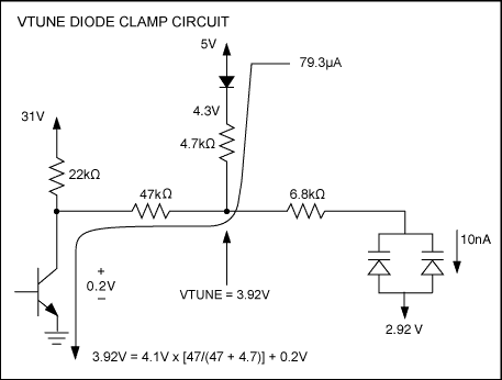
Figure 1. Typical diode clamping circuit
However, the parasitic mode becomes the main problem in the initial power-up sequence. Experiments show that turning off the LO doubler during power-on can resolve parasitic oscillations. The following analysis will explain why turning off the frequency doubler will eliminate the parasitic oscillation in the MAX2104.
Figure 1 shows the charge pump transistor saturation during worst-case steady-state operation. Vtune is clamped to 3.92V to ensure that the oscillator is out of parasitic oscillation mode.
Analysis For example, suppose that the set-top box is initially programmed to lock at 1458MHz and the LO doubler is turned on. In an ideal situation, the PLL works as shown in Figure 2.
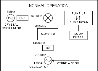
Figure 2. Normal PLL operation
In normal operation, the phase frequency of the crystal and the local oscillator is 625kHz; Vtune is about 10.3V, and the local oscillator oscillates at 729MHz. The frequency doubling circuit doubles it to 1458MHz. The equivalent division ratio is programmed to N = 2332.8. The charge pump collapses to maintain balance, and the charge pump sinks and sinks current as needed.
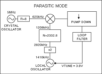
Figure 3. Parasitic mode oscillation
Oscillating in parasitic mode, the local oscillator oscillates at 1410MHz. The local oscillator frequency multiplier is turned on, and this oscillation frequency is doubled to 2820MHz. This will produce a phase discrimination frequency of 1208kHz. Because the crystal phase frequency is much greater than 625kHz, the charge pump sinks as much current as possible to cause the tuning voltage to decrease. This positive feedback keeps the tuning voltage as low as possible. The lower the tuning voltage, the less likely it is to exit the parasitic resonance mode, because the resonant tank has an on-load Q value at the minimum in the fundamental frequency mode oscillation required.
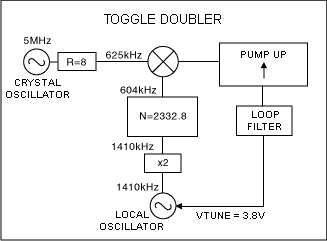
Figure 4. Fixed LO doubler
Figure 4 shows the PLL operation after the LO doubler is turned off. Now the local oscillator is no longer doubled, and the local oscillator comparison frequency is reduced to 604kHz. Because it is lower than the crystal reference phase frequency of 625kHz, the charge pump draws current to increase the tuning voltage. The tuning voltage rose from 3.8V to 31V. When Vtune increases from 3.8V to 31V, the resonant tank's loaded Q value is greatly improved, and it can resonate in the fundamental frequency mode.
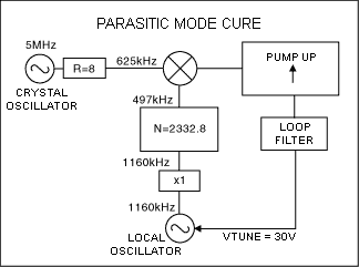
Figure 5. Remedies for parasitic mode
Fig. 5 shows the case of exiting the parasitic mode. Due to positive feedback, Vtune is forced to 30V. The charge pump is in continuous current mode. The resonance circuit reaches the maximum oscillation frequency, about 1160MHz. If the frequency doubler is activated in time at this frequency, the PLL will return to the normal operating mode shown in Figure 1. Conclusion From the above analysis, the following conclusions can be obtained:
The best way to eliminate parasitic mode oscillations during startup is to program the PLL to a frequency where a large Vtune value can be obtained. This will make the tuning voltage higher than the clamping voltage value. When this step is implemented, the Vtune diode clamping circuit will ensure that the tuning voltage is higher than the parasitic mode point where the resonant circuit is easy to enter. Turning off the frequency doubler will eliminate parasitic mode oscillations.
What is Car Ethernet
Car Ethernet is a new local area network technology that uses Ethernet to connect the electronic unit in the car. Unlike traditional Ethernet, which uses 4 unshielded twisted pair cables, car Ethernet can achieve a transmission rate of 100Mbit/s or even 1Gbit/s on a single pair of unshielded twisted pair cables. At the same time, it also meets the requirements of the automotive industry for high reliability, low electromagnetic radiation, low power consumption, bandwidth allocation, low latency and synchronous real-time. The physical layer of on-board Ethernet uses BroadRReach technology, and BroadR-Reach's physical layer (PHY) technology has been standardized by the One-pair Ethernet Alliance (OPEN). Therefore, it is sometimes called Broad RReach (BRR) or OABR (Open Alliance BroadR-Reach). The MAC layer of vehicle Ethernet adopts the IEEE 802.3 interface standard and seamlessly supports widely used high-level network protocols (such as TCP/IP) without any adaptation.
On-board Ethernet protocol architecture
Vehicle-borne Ethernet and its supported upper-layer protocol architecture are shown in Figure 1. Vehicle-borne Ethernet mainly involves OSI layer 1 and Layer 2 technologies, while vehicle-borne Ethernet also supports AVB, TCP/IP, DOIP, SOME/IP and other protocols or application forms.
On-board Ethernet framework
Among them, AVB is an extension of traditional Ethernet functions, which enhances the real-time performance of traditional Ethernet audio and video transmission by adding precise clock synchronization, bandwidth reservation and other protocols, and is a network audio and video real-time transmission technology with great development potential. SOME/IP (Scalable Service-Oriented MiddlewarE on IP) specifies the video communication interface requirements for vehicle camera applications, which can be applied to the field of vehicle cameras, and realizes the mode control of driver assistance cameras through apis.
As an extension of AVB protocol, Time-Sensitive Networking (TSN) introduces related technologies of time-triggered Ethernet, which can efficiently realize the transmission of automotive control information. In addition, the on-board Ethernet of the 1Gbit communication standard also supports Power Over Ethernet (POE) function and Energy-Efficient Ethernet (EEE) function. The POE function provides power for connected terminal devices while transmitting data through twisted pair cables, eliminating the need to connect external power cables to terminals and reducing the complexity of power supply.
On-board Ethernet standardization
In terms of in-vehicle Ethernet standardization, the IEEE802.3 and IEEE802.1 working groups, AUTOSAR, the OPEN Alliance and the AVnu Alliance have played a major role in promoting it.
The IEEE802.3 local area network standard represents the mainstream Ethernet standard in the industry, and the on-board Ethernet technology is developed on the basis of IEEE802.3, so the IEEE is currently the most important international standardization body for on-board Ethernet. In order to meet the requirements of the car, it involves the development of a number of new specifications and the revision of the original specifications within the two working groups of IEEE802 and 802.1, including PHY specifications, AVB specifications, and single-wire to data line power supply. In addition, AVB related to AV transmission, timing synchronization and other specifications also need to be standardized by other technical committees of IEEE, such as IEEE1722 and IEEE1588.
OPEN Alliance
The OPEN Industry Alliance was launched in November 2011 by Broadcom, NXP, and BMW to promote the application of Ethernet-based technology standards to in-car connectivity. The main standardization goal is to develop a 100Mbit/s BroadR-R physical layer standard and develop OPEN interoperability requirements.
AUTOSAR
AUTOSAR is a consortium of automotive manufacturers, suppliers, and tool developers that aims to develop an open, standardized automotive software architecture, and the AUTOSAR specification already includes the automotive TCP/UDP/IP protocol stack.
AVnu
The AVnu Alliance was formed by Broadcom in collaboration with Cisco, Harman and Intel to promote the IEEE 802.1 AVB standard and the Time Synchronization Network (TSN) standard, establish a certification system, and address important technical and performance issues such as precise timing, real-time synchronization, bandwidth reservation, and traffic shaping.
Vehicle Router,Vehicle 4G Router,Vehicle 4G Wireless Router,Vehicle Wifi Router
Shenzhen MovingComm Technology Co., Ltd. , https://www.szmovingcomm.com