Micro-electromechanical (MEMS) gyroscopes are extensively used in aviation, automotive systems, and consumer electronics. They are primarily categorized into linear vibrating gyros and rotating vibrating gyros based on their vibration structures. As the cost, power consumption, and size of MEMS gyros continue to decrease, new demands such as higher precision and faster sampling rates have emerged for their digitalization schemes. To operate at high frequencies, the digital circuits must support high sampling rates. Currently, the digitization of MEMS gyros is typically achieved using embedded Field Programmable Gate Arrays (FPGAs), Digital Signal Processors (DSPs), or a combination of both.
Finally, the MEMS gyro undergoes testing on a dedicated platform, enabling signal demodulation and control to be handled on the PC side. This approach offers greater convenience compared to traditional FPGA or DSP-based solutions. High-speed data transmission between the PC and capture card is facilitated via the PCIe (PCI Express) bus, with a maximum control delay of less than 10 microseconds.
1. Low-Speed Optimization Design for Real-Time Control Systems
Real-time performance is a critical factor in the measurement and control system of a gyro. This section focuses on designing and optimizing the low latency and stability of the control system. The first part of the low-latency optimization includes both hardware and software improvements. Hardware optimization involves selecting appropriate high-speed buses and managing their transmission control methods. On the software side, it includes optimizing operating system drivers and refining control algorithms. The second part of the optimization focuses on ensuring the stability of the computer-based real-time control system, allowing it to consistently generate output signals. In practical engineering, the system must avoid being affected by interrupt delays or fluctuating transmission delays when controlling the gyro equipment.
1.1 Low-Latency Optimization in Data Transmission
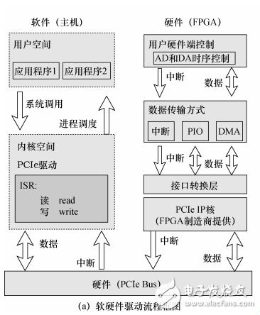
Figure 1: Low-latency optimization scheme for real-time measurement and control platform
Figure 1a illustrates the hardware and software architecture along with the data flow of the real-time measurement and control platform. Once a hardware interrupt is triggered, the data collected by the ADC must pass through an interface conversion layer, the PCIe IP core of the FPGA, and the PCIe bus before reaching the computer's I/O memory space. After memory address mapping is completed, the user program can read the data from memory for further processing. In actual multi-threaded data transfers, additional delays occur, as shown in Figure 1b. These include interrupt latency, thread latency, and thread context switch latency. Interrupt latency refers to the time difference between the execution of the hardware interrupt and the first instruction in the Interrupt Service Routine (ISR). It is mainly influenced by the kernel architecture, CPU frequency, and load. Due to thread scheduling, the kernel requires time to save and restore the thread context, acquire or release semaphores, and perform other related tasks. Thread latency is defined as the time difference between the moment a waiting thread is signaled in the ISR and the moment it begins executing its first instruction. The thread context switch time is the time difference between the first instruction of one thread and the first instruction of another thread.
Stage Lights Controller,Stage Lighting Dimmer,Stage Light Dimmer Controller,Moving Head Light Controller
Guangzhou Cheng Wen Photoelectric Technology Co., Ltd. , https://www.cwledwall.com