Basic Circuit
A DC stabilized power supply typically operates using a 220V AC input. This voltage is first stepped down using a transformer, then rectified to convert it into direct current (DC). After rectification, the output is filtered to smooth out the pulsating DC, and finally, a voltage regulator ensures that the output remains stable. The transformer, rectifier, and filter circuits together form the basic structure of a DC power supply. Without these components, the voltage regulator would not function properly.
1. Transformer Circuit
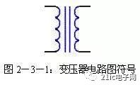
The transformer is a key component in the power supply system. It converts the incoming AC voltage to a suitable level for the downstream circuit. A typical power transformer consists of a primary winding, a secondary winding, and an iron core. The primary winding receives the AC voltage from the power source, while the secondary winding provides the desired AC output. The transformer works by converting electrical energy into magnetic energy and back into electrical energy. The alternating current in the primary winding creates an alternating magnetic field in the core, which induces a voltage in the secondary winding. When the secondary is connected to a load, a current flows through the circuit. The symbol for a transformer is shown in Figure 2-3-1.
2. Rectifier Circuit
After the AC voltage is transformed, it still needs to be converted into DC for use in electronic circuits. This process is done using a rectifier circuit. Diodes are commonly used in rectifiers due to their ability to allow current to flow in only one direction, thus converting AC into pulsating DC.
(1) Half-Wave Rectifier Circuit
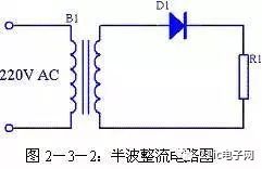
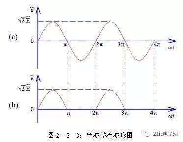
The half-wave rectifier circuit is shown in Figure 2-3-2. Here, B1 is the transformer, D1 is the diode, and R1 is the load. The secondary winding of B1 produces a sinusoidal AC voltage. During the positive half-cycle (from 0 to π), the upper end of B1 is negative, and the lower end is positive. This causes D1 to conduct, allowing current to flow through R1. In the negative half-cycle (π to 2π), the polarity reverses, and D1 does not conduct, so no current flows through R1. This results in a pulsating DC waveform, as shown in Figure 2-3-3(b). However, since only half of the AC cycle is used, the efficiency is low. This type of rectifier is mainly used in high-voltage, low-current applications.
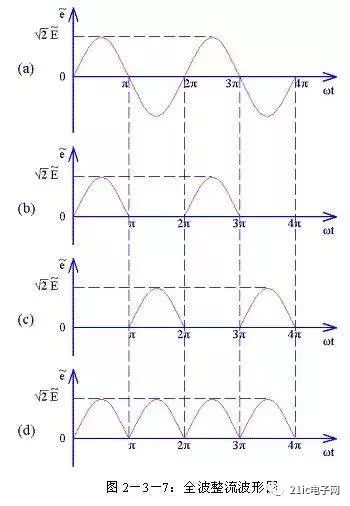
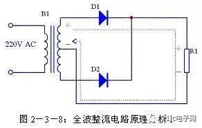
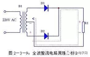
(2) Full-Wave Rectifier Circuit
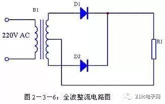
To improve efficiency, full-wave rectifiers use both the positive and negative halves of the AC cycle. This is achieved by using a center-tapped transformer and two diodes. During the positive half-cycle, one diode conducts, and during the negative half-cycle, the other conducts. This results in a more continuous DC output. The circuit diagram and waveforms are shown in Figures 2-3-6 to 2-3-9.
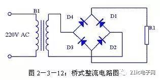
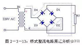
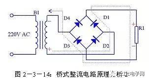
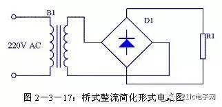
(3) Bridge Rectifier Circuit
The bridge rectifier eliminates the need for a center-tapped transformer by using four diodes arranged in a bridge configuration. This allows both halves of the AC cycle to be used without requiring a special transformer. The circuit is efficient and widely used in power supplies. The operation and waveforms are illustrated in Figures 2-3-13 to 2-3-16.
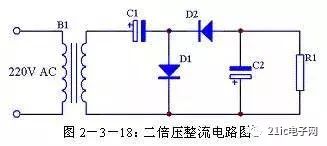
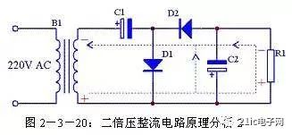
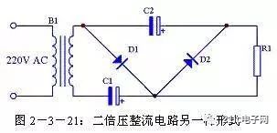
(4) Voltage Doubler Circuit
If a higher output voltage than the input is needed, a voltage doubler circuit can be used. This circuit uses capacitors and diodes to double the peak voltage of the AC input. The principle is shown in Figures 2-3-18 to 2-3-21, where capacitors charge and discharge in sequence to produce a higher DC output.
3. Filter Circuit
After rectification, the output is a pulsating DC signal. To make it suitable for electronic circuits, this ripple must be reduced. Filters are used to smooth the output. Common types include capacitor filters, inductor filters, RC filters, LC filters, and active filters.
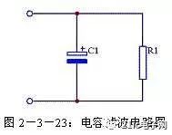
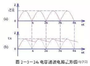
(1) Capacitor Filter Circuit
A capacitor filter uses the charging and discharging behavior of a capacitor to reduce ripple. When the rectified voltage rises, the capacitor charges; when it falls, it discharges slowly. This results in a smoother DC output. The circuit and waveform are shown in Figures 2-3-23 and 2-3-24.
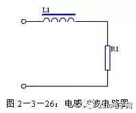
(2) Inductor Filter Circuit
An inductor filter uses the property of inductors to oppose changes in current. This helps to smooth out the ripple. These filters are especially useful in high-current applications. The circuit is shown in Figure 2-3-26.
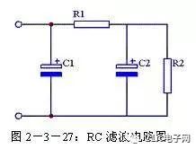
(3) RC Filter Circuit
This filter combines resistors and capacitors to further reduce ripple. It is also known as a π-type filter. The resistor helps to dampen the AC component before it reaches the load. The circuit is shown in Figure 2-3-27.
(4) LC Filter Circuit
The LC filter combines the advantages of both capacitors and inductors. It provides better ripple reduction and stronger load capacity. The circuit is shown in Figure 2-3-28.

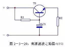
(5) Active Filter Circuit
For high-performance filtering, active filters use transistors or operational amplifiers to increase the effective capacitance. This allows for more efficient ripple suppression without requiring large capacitors. The circuit is shown in Figure 2-3-29.
4. Summary of Rectifier and Filter Circuits
(1) Comparison of Rectifier Performance
A comparison of different rectifier circuits is shown in Figure 2-3-29. Parameters such as output voltage, current, and diode drop are included.
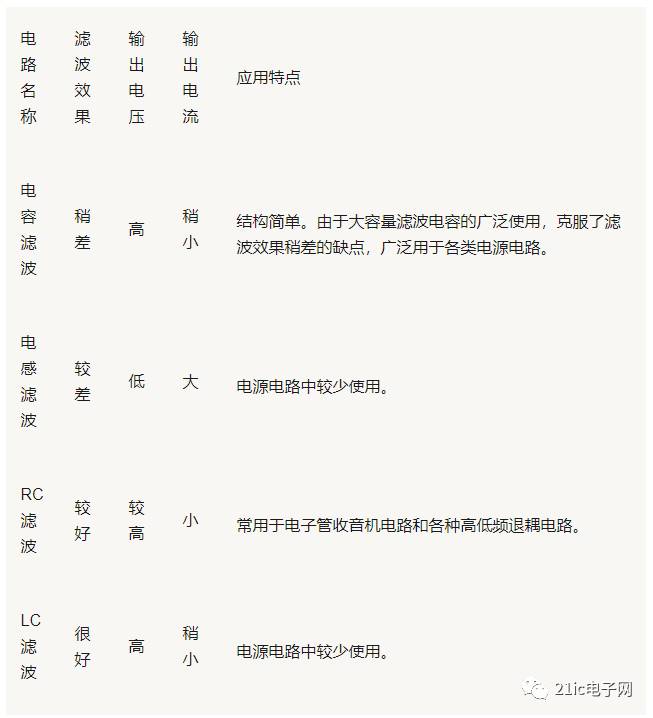
(2) Comparison of Passive Filter Performance
Passive filters vary in performance depending on the components used. The comparison is shown in Figure 2-3-30.
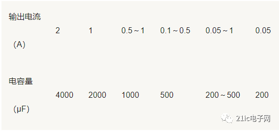
(3) Relationship Between Capacitor Filter and Output Current
The relationship between the filter capacitance and the output current is shown in Figure 2-3-31.
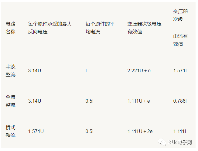
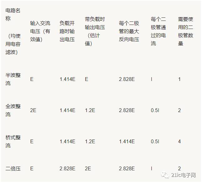
(4) Calculation Table for Common Rectifier and Filter Circuits
A table summarizing the calculations for common rectifier and filter circuits is shown in Figure 2-3-32.

Whaylan 600W portale power stations have Large capacity, high endurance, a variety of ports, at any time for your need to charge the equipment. Completely say goodbye to the anxiety of outdoor electricity and devote yourself to an outdoor activity. At the same time, it can be equipped with solar panels to charge the power supply. The energy storage technology of lithium battery is combined with the clean renewable energy of solar energy to truly realize the enjoyment from day to night.
600W power station,solar station,bluetti 600w,lithium generator
suzhou whaylan new energy technology co., ltd , https://www.xinlingvideo.com