Basic Circuit
A DC stabilized power supply typically operates using a 220V AC input. This voltage is first stepped down by a transformer, then rectified and filtered before being regulated to provide a stable DC output. The transformer, rectification, and filtering stages form the fundamental building blocks of a DC power supply. Without these components, the voltage regulator would not function properly.
1. Transformer Circuit
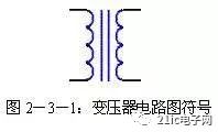
The transformer is a crucial component in DC power supplies, designed to step up or step down the AC voltage from the mains to a level suitable for the rest of the circuit. It consists of a primary winding, secondary winding, and an iron core. The primary winding receives the AC input, while the secondary winding delivers the transformed AC voltage. The transformer works by converting electrical energy into magnetic energy and then back into electrical energy. This process allows the AC signal to be transferred efficiently between the two windings. The symbol for a transformer is shown in Figure 2-3-1.
2. Rectifier Circuit
After the AC voltage is transformed, it still needs to be converted into DC for use in electronic circuits. This is where the rectifier comes in. A rectifier uses the unidirectional conductivity of diodes to convert AC into pulsating DC. There are several types of rectifier circuits, including half-wave, full-wave, and bridge rectifiers.
(1) Half-Wave Rectifier Circuit
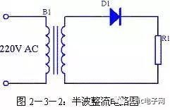
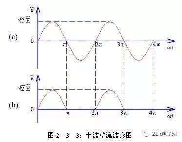
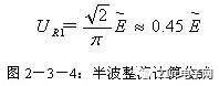
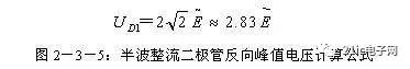
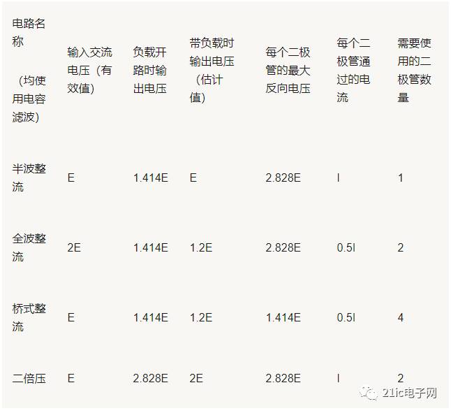
The half-wave rectifier circuit is the simplest type. As shown in Figure 2-3-2, it uses a single diode to allow only one half of the AC waveform to pass through. During the positive half-cycle, the diode conducts, allowing current to flow through the load. During the negative half-cycle, the diode blocks the current. This results in a pulsating DC output, which is not ideal for most applications due to its low efficiency and high ripple. The formula for the output voltage is given below, and the peak inverse voltage (PIV) that the diode must withstand is also calculated.
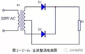
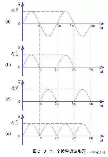
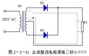
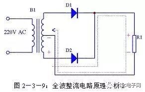
(2) Full-Wave Rectifier Circuit
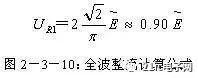
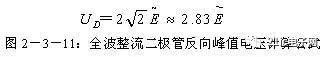
To improve efficiency, full-wave rectifiers are used, which utilize both the positive and negative halves of the AC waveform. This is achieved by using a center-tapped transformer and two diodes. During each half-cycle, one diode conducts, ensuring that the output remains in one direction. This results in a smoother DC output compared to the half-wave version. The formulas for the output voltage and PIV are also provided.
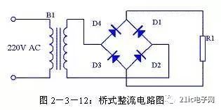
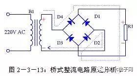
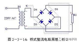
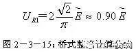
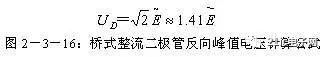
(3) Bridge Rectifier Circuit
The bridge rectifier is another common configuration that eliminates the need for a center-tapped transformer. Instead, it uses four diodes arranged in a bridge configuration. This allows the circuit to operate with a standard transformer and provides a more efficient and compact design. The operation of the bridge rectifier is explained with waveforms and formulas.
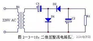
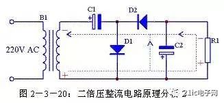
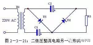
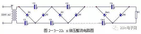
(4) Voltage Doubler Circuit
For applications requiring higher voltages, a voltage doubler circuit can be used. This circuit uses capacitors and diodes to double the peak voltage of the AC input. It is especially useful in high-voltage applications. The working principle and waveforms are illustrated in the figures below.
3. Filter Circuit
After rectification, the output is a pulsating DC signal with significant AC ripple. To smooth this out, a filter circuit is used. Common types include capacitor filters, inductor filters, RC filters, LC filters, and active filters.
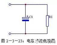
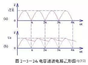
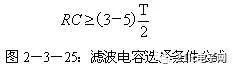
(1) Capacitor Filter Circuit
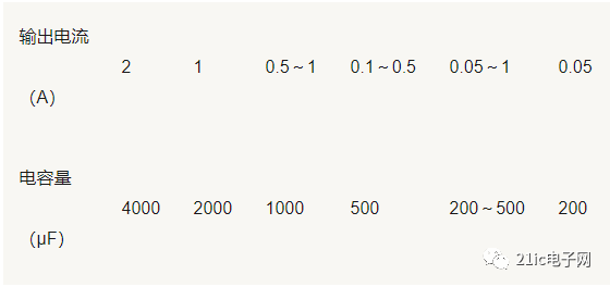
A capacitor filter uses the charging and discharging characteristics of a capacitor to reduce ripple. The capacitor charges during the rising portion of the waveform and discharges slowly during the falling part. This results in a smoother DC output. The required capacitance depends on the load and frequency.
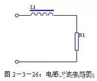
(2) Inductive Filter Circuit
An inductive filter uses an inductor to oppose changes in current, thereby reducing ripple. It is particularly effective in high-current applications but is bulkier and more expensive than capacitor filters.
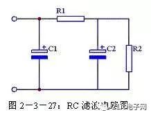
(3) RC Filter Circuit
An RC filter combines a resistor and a capacitor to further reduce ripple. It is often used in multi-stage filtering systems. However, the resistor must be chosen carefully to avoid excessive voltage drop.
(4) LC Filter Circuit
An LC filter combines the advantages of both inductors and capacitors. It offers better ripple suppression and higher load capacity, making it suitable for high-power applications.

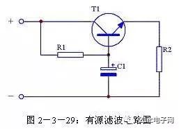
(5) Active Filter Circuit
An active filter uses transistors or operational amplifiers to enhance filtering performance. It effectively increases the equivalent capacitance, providing a cleaner DC output. However, it requires careful design to ensure stability and proper biasing.
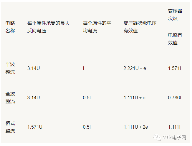
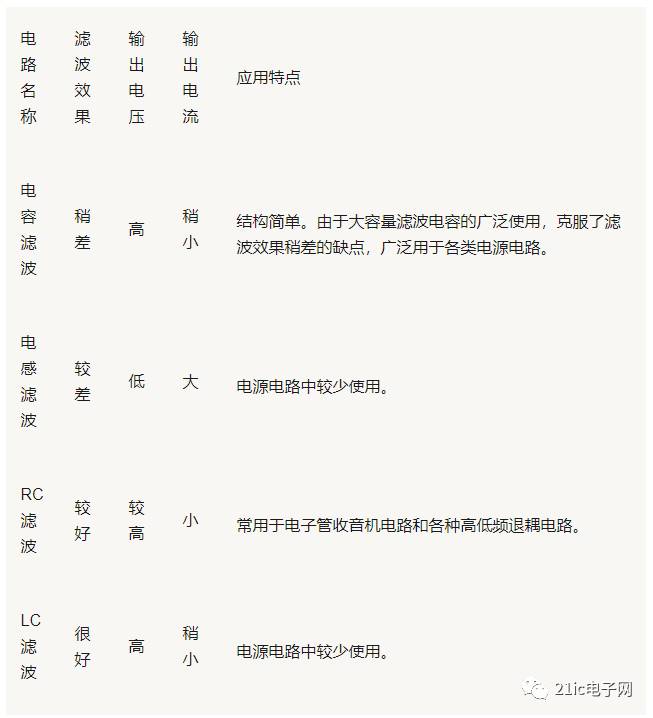
4. Summary of Rectifier and Filter Circuits
This section compares the performance of various rectifier and filter circuits, including their voltage, current, and ripple characteristics. Tables and graphs illustrate the differences between each configuration, helping engineers choose the most suitable option for their application.
1KW-8KW Power Inverter
Use double MCU design,the product provides different charge voltages and charge currents to realize charge management for batteries of different types.Its mains supply preferred mode,energy--saving mode and battery preferred mode are all settable,thus making it easy to meet users' different application needs.It has an LCD to show operation status.It is widely applied to families,schools,streets,frontier defense,pasturing areas,industrial equipment,military vehicle--borne equipment,ambulances,police cars,ships,ect.


Nkm Hybrid Inverter With Mppt Charge,Inverter Power Inverter,Hybrid Inverter Charger,Hybrid Grid Tie Inverter
suzhou whaylan new energy technology co., ltd , https://www.xinlingvideo.com