Toshiba Lighting and Sharp's new LED bulb internal structure reveals (1)
Toshiba and Sharp's new LED bulbs are revealed (2): the radiator structure is different
The internal structure of the new LED bulb is revealed (3): the size of the power supply circuit is significantly different
The internal structure of the new LED bulb is revealed (4): changing the heat dissipation method to achieve low cost
The internal structure of the new LED bulb is revealed (5): improving the heat dissipation of the LED package
Power circuit size is significantly different
A power circuit board and a resin case are mounted inside the heat sink. Figure 6 shows the situation after removing the metal cover under the Toshiba Illuminated LED bulb. The power circuit board is inserted into a resin case that is fixed to the heat sink with one screw.
Figure 6: The lower power circuit board of the Toshiba Illumination LED bulb is inserted into the resin case. The resin case is fixed to the heat sink with one screw.
The bottom plate of the power circuit is a rectangular phenolic paper base plate, and the resin case is substantially close to the cylindrical shape (Fig. 7). A resin case is disposed between the bottom plate and the heat sink to ensure insulation between the two.
Figure 7: Resin shell of the Toshiba Illuminated LED Bulb and the power circuit bottom plate Resin shell has an open part only on the metal cover side (the right side in the figure), which ensures the insulation of the power circuit bottom plate and the heat sink. The power circuit bottom plate has a rectangular shape and is connected to the LED bottom plate through a connector.
Figure 8 is a section of Sharp's LED bulb heatsink. Because the filling material is hard, it takes a lot of time to remove it from above, so the radiator is cut directly.
Figure 8: The section of the Sharp LED bulb is filled with a dense filling material inside the heat sink, and the power circuit board and resin case are completely covered.
After the heat sink is dissected, as the filling material is gradually peeled off, the shape of the power supply circuit board and the resin case (hereinafter, the resin case A) supporting the bottom plate gradually appear (Fig. 9). The power circuit board is shaped like a badminton racket and has the same dimensions as the inner diameter of the heat sink.
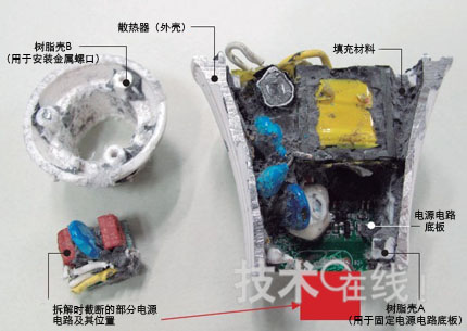
Figure 9: After the power circuit board of the Sharp LED bulb clears the filler material, the components mounted on the power circuit board are in front of the eyes. The power circuit board is in the shape of a "badminton racket" and extends to the lowermost resin case A (for mounting the metal cover).
Sharp's power circuit board is made of epoxy glass, which is much larger than the Toshiba lighting floor. Is this due to the size of the backplane that limits the height of the heat sink channel? Or is it necessary to size the components of the power circuit and the size of the backplane in order to achieve the optimal balance of cost and heat generation in a limited space? These questions failed to get an answer. But in summary, the heat generated by the power circuit backplane needs to be conducted to the heat sink. Sharp said, "In order to support the small lamp holders such as E17 and E11 in the future, the miniaturization of the base plate is currently under discussion."
The resin case A is a side which is cut only by retaining the annular shape of the upper end and the lower end of the cylindrical shape. The other side of the power circuit component has a larger opening to facilitate heat transfer to the heat sink.
The assembly procedure of the LED bulb is presumed as follows.
Toshiba lighting process: 1 fixed resin shell on the heat sink (1 screw fixed); 2 inserted into the power circuit bottom board; 3 installed metal cover (including connection wiring); 4 fixed LED substrate (2 screws fixed); Use a connector to connect the wiring; 6 connect the spherical lampshade.
Sharp's process is: 1 fixing the resin case B on the heat sink; (3 screws fixed); 2 inserting the resin case A into the heat sink; 3 inserting the power circuit bottom plate in the resin case A; 4 mounting the metal cover (including the connection) Wiring); 5 injection filling material; 6 configuration O ring; 7 fixed metal plate (3 screws fixed); 8 fixed LED substrate (3 screws fixed); 9 wiring welding; 10 connected spherical lampshade.
Unlike Toshiba Lighting, which uses a heat sink as the center and installs components in the upper and lower directions, Sharp uses a step-by-step installation from bottom to top.
Although Sharp has many processes, it is manufactured in factories in China, so many processes are still feasible. Toshiba Lighting is assembled at a factory in Japan, so it is necessary to reduce the number of components and assembly man-hours in terms of cost. (To be continued)
Toshiba Lighting and Sharp's new LED bulb internal structure reveals (1)
Toshiba and Sharp's new LED bulbs are revealed (2): the radiator structure is different
The internal structure of the new LED bulb is revealed (3): the size of the power supply circuit is significantly different
The internal structure of the new LED bulb is revealed (4): changing the heat dissipation method to achieve low cost
The internal structure of the new LED bulb is revealed (5): improving the heat dissipation of the LED package
33,35kV Switchboards Switchgears
Vcb Switchgear,Witchgear,High Tension Switchgear,Switchgear
First Electrical Group Co., Ltd. , http://www.cntransformersupplier.com