Research and Experiment of ZigBee Wireless Sensor Network
introduction
Someone translated ZigBee into "Zigbee", one of the standards of Wireless Personal Area Networks (Wireless Personal Area Networks, WPAN), which was announced on June 27, 2005. In addition to the logical link control (Logic Link Control, LLC) layer, the media access control layer (MAC), and the physical layer using the IEEE 802.15.4 standard published in October 2003, the ZigBee standard protocol establishes the application layer and network layer , And security encryption service standards for MAC, application layer and network layer.
Wireless applications represented by sensors and self-organizing networks do not require high transmission bandwidth, but require low transmission delay and extremely low power consumption, enabling users to have longer battery life and more devices Array. At present, there is an urgent need for a special standard that conforms to sensors and low-end, control-oriented, and simple applications, and the appearance of Zigbee just solved this problem. Zigbee has many advantages such as high communication efficiency, low complexity, low power consumption, low speed, low cost, high security and full digitalization. These advantages make Zigbee and wireless sensor network perfectly combined. At present, the research and development of wireless sensor networks based on Zigbee technology have received more and more attention.
1 Zigbee protocol terminology
Profile: The profile of the Zigbee protocol is a description of logical components and related interfaces. It is a convention or guideline for an application category. Usually no program code is associated with the configuration file.
Attribute: Each type of data communicated between devices, such as the state of a switch or the value of a thermometer, can be called an attribute. Each attribute can get a unique ID value.
Cluster: A collection of multiple attributes forms a cluster, and each cluster also has a unique ID. Although attribute information is usually transmitted between individuals, the so-called logical component interface refers to cluster-level operations, not attribute-level operations.
Endpoint: Each code function block that supports one or more clusters is called an endpoint. Different devices communicate through their terminals and supported clusters.
The configuration file defines the attribute ID and cluster ID to make it look like a certain characteristic of the device. Taking the home intelligent control system as an example, the lamp configuration file sets the cluster OnOffDRC of the remote control device to contain an attribute OnOff, and the attribute is an unsigned 8-bit value. The value 0XFF means "on", 0X00 is off, and 0XF0 Is invalid. Usually, the configuration file also defines for the device, which clusters are mandatory managed and which clusters are optional. In addition, the configuration file also defines some optional Zigbee protocol hosting services.
Based on the services defined by the cluster and configuration, users can use the attributes defined in the configuration file to write the required functions. Rewrite your own program code. Therefore, the configuration file makes ZigBee devices interoperable. Any node that follows a standard configuration file can interoperate with other nodes that implement the same configuration file. That is to say, based on the design using the same standard configuration file, even if the manufacturer of the switch is different from the manufacturer of the controller, the products they produce can still achieve cooperative operation.
Taking light control in a home intelligent system as an example, the light configuration file defines six devices, and the protocol stack supports this configuration through a header file with the following information: profile ID, device ID and version, cluster ID, Attribute ID, attribute data type.
The following figure (1) shows the relationship between different terms. For the lighting configuration of the home intelligent control system, two devices are shown in the figure. Each device has a terminal. There is only one input cluster in the terminal of the load switching controller, while the remote switching control terminal has two clusters, one for each input and one for output. Data transmission is based on clusters.
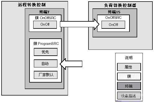
figure 1)
2 Zigbee protocol stack structure
As shown in (2), the different layers of the ZigBee stack communicate with the 802.15.4 MAC through a service access point (SAP). SAP is the interface between the services provided by a specific layer and the upper layer. Most layers of the ZigBee stack have two interfaces: data entity interface and management entity interface. The goal of the data entity interface is to provide the required conventional data services to the upper layer. The goal of the management entity interface is to provide the upper layer with access to internal layer parameters, configuration and management data services. In the figure, APSDE-SAP and NLDE-SAP are data entity interfaces, while APSME-SAP and NLME-SAP are management entity interfaces.
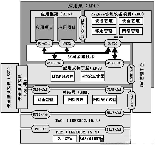
figure 2)
3 Message format and frame format of Zigbee protocol
3.1 Message format
A Zigbee message consists of 127 bytes, which mainly includes the following parts:
MAC header: This header contains the source and destination addresses of the currently transmitted message. If the message is routed, the address may not be the actual address, and the generation and use of the header is transparent to the application code.
NWK header: This header contains the actual source address and final destination address of the message. The generation and use of this header are transparent to the application code.
APS header: This header contains the configuration ID, cluster ID, and destination terminal of the current message. Similarly, the generation and use of headers are transparent.
Payload: This field contains the Zigbee protocol frame to be processed by the application layer.
3. 2 ZigBee agreement frame format
The Zigbee protocol defines two frame formats: KVP key value pair and MSG message frame.
KVP: It is a special data transmission mechanism defined by the ZigBee specification. It uses a stipulation to standardize the data transmission format and content, and is mainly used to transmit simpler variable value formats.
MSG: It is a special data transmission mechanism defined by the ZigBee specification. It does not make more regulations on the data transmission format and content. It is mainly used for a transmission mechanism with a large amount of data such as dedicated data streams or file data.
KVP frame is a special and more standardized information format, which adopts the form of key-value pairs and transmits data in a prescribed format. It is usually used to transmit a simple attribute variable value; MSG frames do not have a specific format, and are usually used for the transmission of multiple information and complex information. KVP and MSG are two data formats in communication. If you compare a frame to an email, then the envelope, stamp, address name and other information are the frame header and frame tail, and the content of the letter is a specific data format KVP or MSG. According to the profile of the specific application (Profile), KVP is generally used for simple attribute data, and MSG is used for more complex information with large data volume.
4 Addressing
4.1 Two types of addresses in Zigbee protocol
Each node of the Zigbee network protocol has two addresses: a 64-bit IEEE MAC address and a 16-bit network address.
Each device that uses the Zigbee protocol to communicate has a unique 64-bit MAC address in the world. This address is composed of 24-bit UIDs and 40-bit manufacturer-assigned addresses. OUIs can be allocated by IEEE through purchase. Because all OUIs are specified by IEEE Therefore, the 64-bit IEEE MAC address is globally unique.
When devices perform network join operations, they will use their extended addresses to communicate. After successfully joining the Zigbee network, the network will assign a 16-bit network address to the device. Therefore, the device can use this address to communicate with other devices in the network.
4.2 Addressing mode
Unicast: When unicasting a message, the MAC header of the packet should contain the address of the destination node. Only when the address of the receiving device is known, the message can be sent in unicast.
Broadcasting: To send a message by broadcasting, the destination address field in the MAC header of the packet should be set to 0XFF. At this time, all radio frequency transceiver enabled terminals can receive the information.
This addressing mode can be used to join a network, search for routes, and perform other search functions for the ZigBee protocol. The ZigBee protocol implements a passive response mode for broadcast packets. That is, when a device generates or forwards a broadcast packet, it will listen to the forwarding conditions of all neighbors. If all neighbors do not copy the packet within the response time limit, the device will forward the packet repeatedly until it hears that the packet has been forwarded by all neighbors or the broadcast transmission time is exhausted.
5 Data transmission mechanism
For a non-beacon network, when a device wants to send a data frame, it will wait for the channel to be idle until the device detects that the channel is empty and the device will transmit the frame.
If the destination device is a FFD full-function device, its receiver should always remain on so that other devices can transmit data to it at any time. However, if the device is an RFD reduced-function device, the device will turn off the transceiver to save energy when there is no operation. At this time, the RFD device cannot receive any data. Therefore, other devices can only request or send data to the RFD device through the FFD parents of the RFD. Until the RFD powers up the RX transceiver, it will request its own information data from the parents. If there is information sent to the child in the parent buffer, the information will be sent to the child's device. This operating mode can reduce the power consumption of the RFD, but the corresponding parent FFD node should have enough RAM space to buffer information for the child device. If the child device does not request information within the specified time, the information will be lost.
6 Formation of Zigbee wireless network
First, a new Zigbee network is established by the Zigbee coordinator. At the beginning, the Zigbee coordinator will search for other Zigbee coordinators in the allowed channel. And based on the channel energy and network number detected in each allowed channel, select a unique 16-bit PAN ID to build your own network. Once a new network is established, Zigbee routers and terminal devices can be added to the network.
After the network is formed, network overlap and PAN ID conflicts may occur. The coordinator can initialize the PAN ID conflict resolution procedure, change the PAN ID and channel of a coordinator, and modify all its child devices accordingly. Usually, the Zigbee device will store the information of other nodes in the network in a non-volatile storage space-neighbor table. After power-on, if the child's device has ever joined the network, the device will execute the orphan notification procedure to lock the previously joined network. The device that has received the orphan notification checks its neighbor list and determines whether the device is its child. If so, the device will notify the child device of its location in the network, otherwise the child device will join the network as a new device. Afterwards, the child device will generate a potential parent list and try to join the existing network with the appropriate depth.
Generally, the time it takes for a device to detect channel energy and the network available for each channel can be determined by ScanDuraTIon scanning continuous parameters. Generally, it takes 1 minute for a device to perform a scan request. For Zigbee routers and terminal devices, Only one scan is needed to determine which network to join. The coordinator needs to scan twice, once to sample the channel energy, and once to determine the existing network.
Deluxe Rice Cooker was one of electric type rice cooker , but it`s the most popular type of electric rice cooker . especially famous in Southeast Asia area with its good appearances with various functions. Not only its outer shell could be customized with different demands, but also it speeding cooking , saving times and electricity, enhancing our lifestyle
Features
The inner pot is made of solid and durable aluminum alloy of high intensity , such as non-stick inner pot , stainless steel inner pot and honeycomb patterned inner pot with non-stick coating.
There are some models that use stainless steel instead of aluminium .Various other materials, such as copper, pure carbon, ceramic, and diamond powder coating, may be used for higher heat conductivity or better taste.
Applications
Multifunction , can cooking rice, soup and much more. added cooking versatility with supplied steam tray.
Some rice cookers have settings for congee, a type of rice porridge called okayu in Japanese, Juk in Korea, and zhou in Chinese.
More elaborate recipes are possible using a rice cooker, and there are cookbooks devoted entirely to dishes prepared using a rice cooker. It is possible to cook soups, stews or sponge cakes in electric rice cookers. By simply adding ingredients and setting it to "warm", a rice cooker cooks the contents at about 65 °C (150 °F). In a few hours, the stew is fully cooked and ready to eat.
Deluxe Rice Cooker
Deluxe Rice Cooker,Cylinder Rice Cooker,Mini Rice Cooker,Stainless Steel Rice Cooker
Guangzhou Taipeng Electrical Appliances Technology CO., LTD. , https://www.taipengelectric.com