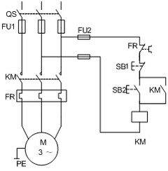
Circuit controlled by a knife switch as main protection

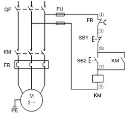
Circuit protected by air switch as main circuit
The working process begins when the start button SB2 is pressed, which energizes the contactor KM coil. This causes the main contacts to close, allowing the motor to run. At the same time, an auxiliary normally open contact closes, creating a self-locking effect. Power flows through FU1 → SB1 normally closed → KM normally open contact → contactor coil → FU2. Once SB2 is released, the KM remains energized due to this self-locking mechanism. When the stop button SB1 is pressed, the normally closed contact opens, de-energizing the KM coil. This results in the opening of both the main and auxiliary contacts, stopping the motor. The thermal relay FR acts as an overload protection device. If the motor becomes overloaded or experiences excessive current, the bimetallic strip inside the FR heats up, causing the normally closed contact to open. This de-energizes the KM coil and stops the motor.
Each component plays a specific role in ensuring safe and efficient motor operation. It's essential to select the right electrical devices based on the motor's rated capacity. For example, the knife switch (QS or QF) is used for power control and should be rated at three times the motor’s rated current. An air switch provides short-circuit protection and can be chosen to match or slightly exceed the motor’s rated current. Fuses (FU) are used for short-circuit protection and are typically selected within a range of 1.5 to 2.5 times the motor’s rated current. The AC contactor (KM) controls the motor’s on/off function and includes voltage loss protection. Its rated current should be between 1.3 and 2 times the motor’s rated current. The thermal relay (FR) provides overload protection. The thermal element’s rated current should be between 1 and 1.5 times the motor’s rated current, with the relay itself being at least equal to the thermal element’s rating.
The thermal relay has two reset modes: automatic and manual. In automatic mode, it resets automatically after about 5 minutes of cooling. In manual mode, you need to press the reset button after 2 minutes. Changing the reset mode without proper understanding may lead to operational issues, such as unintended restarts. Therefore, it’s not advisable to change the reset mode arbitrarily.
For wiring, the main circuit wires should be selected according to the wire gauge requirements, while the control circuit uses insulated copper wires of at least 1.5 mm². The control loop fuse (FU2) can be either 5A or 10A, depending on the application. Finally, the main circuit is protected by the air switch, ensuring safety during operation.
Example: Wiring a 7.5kW motor in one direction. The rated current of the motor is 15A. A knife switch like HQ-60/3 or HK-60/3 can be used. The main circuit fuse could be RClA-30/30 or RL1-60/30. The AC contactor can be B25, CJ20-25, or CJ10-20. A thermal relay like JR16-26/3D with a setting of 15A would work well. The control loop fuse can be RClA-5/3 or RL1-15/2.
Self Wrapping Split Braided Sleeving
f6 self wrapping split braided,Self-closing Wrap,Waved Self-closing Wrap,Polyester High Flame Retardant Self-closing Wrap,Self-wrap braided sleeve
Dongguan Zhonghe Electronics Co., Ltd. , https://www.zhonghesleeving.com