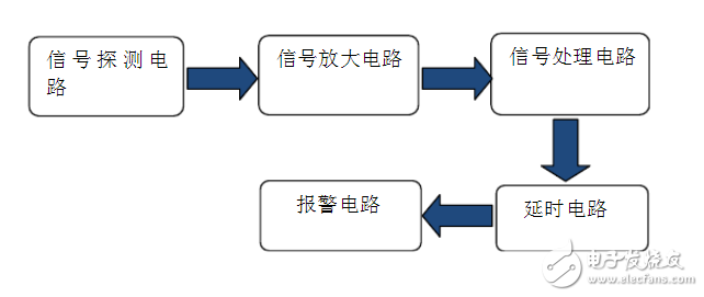
System Block Diagram
The system uses the RE200B pyroelectric sensor as the primary detection element. When a person moves within the sensor's field of view, it generates an electric signal of approximately 0.5V. This signal is then rectified and filtered before being sent to the amplification stage. The amplifying circuit consists of a two-stage operational amplifier, which boosts the signal to about 3.8V and sends it to the signal processing unit. The signal processing circuit compares the incoming signal with a reference signal from pin 9. Since pin 9 is connected to a high-resistance network, it remains at a constant high level. As a result, when motion is detected, the output of the signal processing circuit goes high, triggering the delay circuit. This delay circuit is made up of a resistor-capacitor (RC) network. After a set period, the circuit activates a transistor, which in turn triggers the alarm.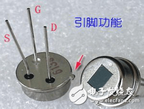
RE200B Physical Map
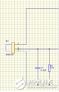
RE200B Schematic
The RE200B is a pyroelectric infrared sensor that detects changes in infrared radiation emitted by objects without direct contact. It converts these changes into electrical signals, which are output from pin 2. To ensure stable operation, a 47kΩ resistor and a 0.1µF capacitor are used around the sensor to filter out noise and interference.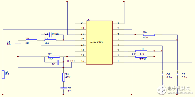
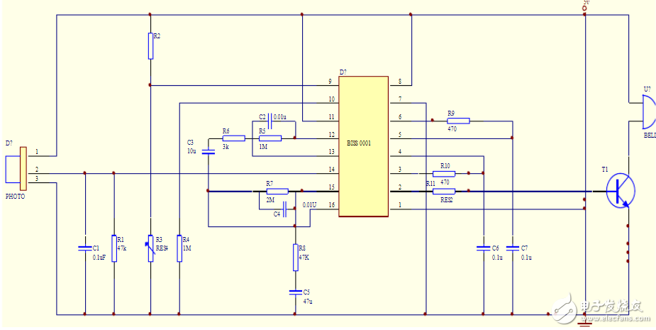
Biss0001 Secondary Amplification and Delay Circuit
The BISS0001 is a high-performance signal processing IC that works in conjunction with the RE200B. It includes a two-stage op-amp, logic circuits, a lockout timer, and a delay timer. When the RE200B detects movement, it outputs a signal of about 0.4V, which is then amplified through the BISS0001’s internal circuitry. The sensitivity of the sensor can be adjusted using external resistors and capacitors connected to pin 15. In this experiment, a 47kΩ resistor and a 47µF capacitor were used to achieve a detection range of up to 1 meter. After two stages of amplification, the signal reaches 3.8V and is compared with the signal from pin 9. Since pin 9 is held at a high level due to a large resistance, the AND gate outputs a high signal when motion is detected. This signal is then processed by the lockout and delay timers. The delay time is calculated as TX ≈ 49152 × R1 × C1. With R1 = 47kΩ and C1 = 10nF, the alarm duration is approximately 23 seconds. The lockout timer prevents false triggering during this period, lasting about 0.012 seconds with R2 = 51kΩ and C2 = 10nF.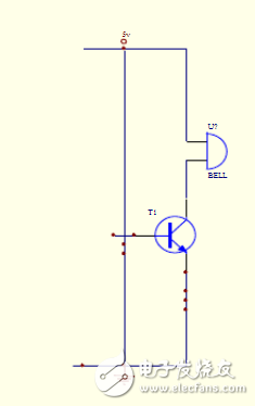
The alarm circuit includes a power supply, a transistor, and a buzzer. The buzzer is connected between the collector of the transistor and the positive terminal of the 5V power supply. The emitter is grounded, while the base is connected to the BISS0001 chip. When the chip detects motion, it outputs a 3.8V signal through a voltage divider, which turns on the transistor and activates the buzzer.
In this experiment, the RE200B was used with the BISS0001 chip to simulate a real-world pyroelectric sensor alarm. When the sensor detects movement, it sends a high-level signal to the BISS0001, which processes it and triggers the buzzer. The combination of the sensor and the processing chip ensures reliable and accurate detection, making it suitable for home or security applications.
Switching Power Supply Transformer
Switching Power Supply Series Transformer,High Quality Switching Power Transformer,Small And Good Transform,High Frequency Transformer Review
Xuzhou Jiuli Electronics Co., Ltd , https://www.xzjiulielectronic.com