l Introduction The click/pop suppressor is a stand-alone device that can be added to the system later in the design to eliminate clicks/pops without changing the original design. The MAX9890 and MAX9892 devices are designed to eliminate the click/pop of the headphone playback system. Different solutions can solve the problem of clicks and clicks generated at different times and from different sources in the design.
This article refers to the address: http://
2 MAX9890 series switching scheme MAX9890 can only eliminate the click/噼噗 caused by the output coupling capacitor. Many headphone playback systems couple the headphone amplifier to the sensor through DC blocking capacitor. In these systems, the main click/pop source is coupled. Charge and discharge of the capacitor when it is turned on and off. The capacitance of the coupling capacitor is usually between 100 and 330 μF, and the “beep†generated by the capacitor charging is very strong. Figure 1 shows the MAX9890 click/pop suppressor.
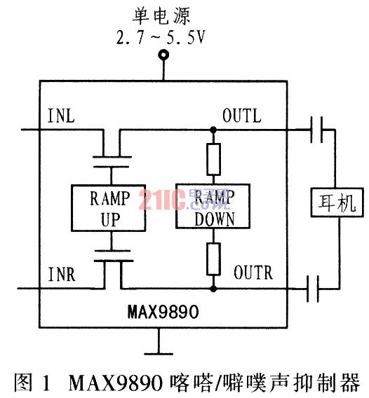
To solve the click/pop problem caused by the coupling capacitor, the MAX9890 slowly charges and discharges the control capacitor at a lower frequency than the audio band. To achieve this goal, the MAX9890 is placed between the amplifier and the coupling capacitor. When turned on, the device slowly applies the DC bias of the headphone amplifier to the capacitor through two switches. When turned off, the coupling capacitor is slowly discharged through the resistor.
The MAX9890's series-switch approach is very effective at suppressing clicks/pops from coupling capacitors, but has no effect on clicks/pops caused by other causes. In addition, this scheme assumes that the headphone impedance on the output side of the coupling capacitor is low. This design is not very efficient for line-out designs with typical loads greater than 10 kΩ.
3 MAX9892 Bypass Mode If the source of the click/pop is not an output coupling capacitor or a line-out output, the ideal solution is the MAX9892. The MAX9892 places a switch between each output and ground, and the switch turns to ground on power-up and power-down. When the switch is closed, the output will be completely muted, eliminating all clicks and clicks, as shown in Figure 2.
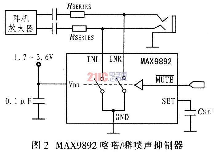
To provide sufficient attenuation, the MAX9892 requires a resistor in series with the amplifier and the socket. This resistor, together with the MAX9892's switch, forms the voltage divider at the output, attenuating the click and click of the amplifier. After the click and click, the MAx9892 is disabled and no longer has any effect on the output signal.
4 Conclusion There are many devices that can suppress audible noise in the design, and their functions are different. Each device is not ideal for any noise suppression application. When selecting a click/pop suppressor, it is necessary to determine which devices are most suitable based on some basic questions, such as: Does the headphone load meet the requirements? Is the coupling capacitor the only source of clicks and clicks in the system? The answer to these two questions is yes, then the MAX9890 is ideal for eliminating clicks and clicks; otherwise, the MAX9892 will be the best solution to the click/pop problem.
The insert splitter is used for the user access point in the FTTX system, which mainly completes the optical fiber end of the residential area or building, and has the functions of optical fiber fixation, stripping, fusion, jumper and shunt, etc. After the splitter, it enters the end user in the form of household optical fiber.
There are currently 1 x N and 2 x N.1 x N and 2 x N evenly inputs the optical signal from a single or double inlet into multiple outlets, or work backward to integrate multiple optical signals into a single or double fiber.
PLC Insert Splitter,Insert Splitter,PLC Optical Splitter,PLC Fiber Splitter
Chengdu Xinruixin Optical Communication Technology Co.,Ltd , http://www.xrxoptics.com