Many people fail to grasp the distinction between signal grounding and power grounding, often assuming they’re the same thing. However, understanding these differences is crucial for ensuring proper circuit functionality. This article won’t delve deeply into the specifics of each type of grounding, but I hope it provides some clarity that proves useful in your learning journey.
The image below illustrates the concept of signal grounding and related techniques:

### What is Signal Ground (SG)?
Signal ground (SG) serves as a reference point for various physical quantity sensors, acting as the zero potential for the signal source and providing a common reference ground (relative zero potential) for signals within the circuit.
Here, the term "signal" typically refers to analog signals or weak digital signals, which are highly sensitive to fluctuations in power supplies or external factors. Such fluctuations can degrade the signal-to-noise ratio (SNR). Particularly for analog signals, any drift in the signal ground can lead to a lower SNR, causing measurement errors or inaccuracies, potentially leading to system design failures.
Therefore, signal ground demands meticulous handling in a system. It should ideally not be directly connected to high-power power grounds, digital grounds, or interference-prone grounds. Isolation is often necessary, especially when dealing with small signals.
### Key Purposes of Signal Circuit Grounding vs. Power Grounding
The primary goal of power grounding in an electrical device is:
1. Ensuring personnel and equipment safety by preventing electric shocks in case of insulation failure.
2. Facilitating system operation, such as neutral-point grounding in AC power systems or positive/neutral grounding in DC systems.
In contrast, the purpose of signal circuit grounding is to guarantee a stable reference potential. To ensure uniform reference potentials across an electronic device, minimize harmful electromagnetic field interference, and ensure stable and reliable operation, the signal circuits in electronic devices should be grounded—referred to as signal ground.
### Differences Between Signal Grounding and Power Grounding
Power ground primarily handles the return path for power loop currents. Typically, the current flowing through power grounds is substantial. Signal ground, however, primarily serves as the return path for communication signals between two chips or modules, with much smaller currents involved. While both are technically GND, the distinction lies in understanding their respective roles when designing PCB layouts. You must clearly define the paths for power and signal returns, then ensure they do not share return paths to prevent issues like common impedance interference.
If power and signal grounds share a return path, a large current on the power ground could create a voltage difference on the signal ground, causing the true potential of the signal ground to rise above 0V. A high signal ground potential might falsely register a signal as high-level when it’s actually low-level.
Additionally, power supplies are inherently noisy, so isolating signal grounds helps prevent misinterpretation due to interference. Proper attention during wiring can mitigate these issues. Even when power and signal grounds are together, the high thresholds of digital circuits usually prevent significant problems.
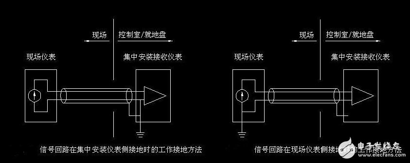
### Shielding Layer Grounding Method and Principle
For a shielded wire, one end is grounded while the other remains suspended. When signal lines have long transmission distances, differences in grounding resistance at both ends or current on the PEN line can create potential differences between the two grounding points. In such cases, grounding both ends introduces interference due to opposing signals. Hence, grounding one end and suspending the other is preferable to avoid interference. Grounding both ends is better for reducing interference but can cause signal distortion.
Key notes:
- Two-layer shielding should be insulated from each other. Failure to do so renders them effectively a single layer.
- The outermost shield's grounding reduces induced potential differences, generating a magnetic flux that cancels induced voltages without the shield.
- The innermost shield is grounded at one end, serving primarily for general static induction prevention.
Standards like "GB 50217-1994" and "GB50057-2000" provide guidelines for grounding control cable metal shields:
- Analog signal loops should avoid multi-point grounding, favoring centralized one-point grounding.
- For electromagnetic induction interference, two-point grounding is preferred; for electrostatic induction, one-point grounding suffices.
- Double-shielded cables should use one-point grounding for both inner and outer shields.
Principles:
1. Single-layer shield: Grounded at one end to avoid potential differences, mainly for static induction.
2. Double-layer shielding: Outer shield grounded at both ends; inner shield grounded at one end. The outer shield reduces magnetic field strength, minimizing induced voltage.
Static interference prevention requires single-point grounding for either single or double-layer shielding due to faster static discharge rates.
Exceptions include:
1. Strong external current interference requiring multi-point grounding for rapid discharge.
2. Safety concerns like electric shock or lightning protection necessitating dual-layer shielding, with the outer shield grounded at multiple points and the inner shield at one point.
### Grounding Methods for Various Signals
Proper grounding design and implementation are critical in control systems. Key ground lines include:
1. Digital ground (logical ground): Zero potential for digital signals.
2. Analog ground: Zero potential for analog signals.
3. Signal ground: Sensor ground.
4. AC ground: AC power supply ground, often a source of noise.
5. DC ground: DC power supply ground.
6. Shielding ground (chassis ground): Prevents static and magnetic field induction.
These ground treatments are vital in system design, installation, and commissioning. Some key considerations:
- Low-frequency circuits are best grounded at one point, while high-frequency circuits require multi-point grounding.
- AC and signal grounds should not share paths due to potential voltage differences.
- Floating grounds offer simplicity but require high insulation resistance; grounding the chassis enhances safety.
- Analog ground connections emphasize shielding and floating techniques.
- Shielding ground connections depend on the purpose of shielding, with electric field shielding connected to earth and magnetic field shielding using high-conductivity materials.
Ultimately, grounding systems should be categorized based on their purposes, avoiding arbitrary connections. Each type should have its own independent grounding subsystem with a common grounding point, connected via a trunk line to achieve total grounding.
This overview aims to provide foundational knowledge. Proper grounding practices require careful consideration of system-specific requirements.
The 16 -port fast charger with 16 USB ports, up to 16 devices at one time. The total power of the total amount of the built -in charger of the 16 -port C -shaped 1U, the output 5V3A/9V2.1A/12V1.7A, supports PD/QC/HuaweiIFCP/PFC, LED turns on the green light, and the red light is charged. Full of electric light.
16 port USB-C hub charges and synchronization up to 16 pieces, smartphones and
Other types of C are equipped with C device. Recommended for schools, office and other
Using a variety of C devices, this unit can provide up to 5V, 3A (15W) power for each port-for charging battery-intensive devices, such as iPad®, iPod®, iPhone®, iPhone® and Android® Tablet computer and smartphone.
16 port USB-C ports can transmit data at a speed of up to 10 GBPS, and the speed of the data is twice as much as USB 3.1 Gen 1. If all ports are used at the same time, each port provides a power of up to 0.9 amp. Because the port conforms to the limitation of BC 1.2, they can pass the charging power of 2.4 Ampel to the mobile device (connected to the power supply).
16-Port USB-C charges, Cabinet type 16 Ports Type C Charger,16 Ports Type-c 1Ucabinet Charger,16 Port USB Hubs,16-port Type-C fast charger
shenzhen ns-idae technology co.,ltd , https://www.best-charger.com