This circuit is designed to utilize solar energy to charge a battery, ensuring a continuous DC voltage output without interruption. It features a constant current charger (IC1), an overcharge protection circuit (IC2 and T1), and a linear switching regulator (IC3).
The constant current charger IC1 limits the charging current to 60mA. When the battery B is at risk of overcharging—due to ample sunlight exposure or minimal load current—the battery voltage increases. This rise in voltage at the sliding terminal of P1 triggers the voltage controller IC2, causing T1 to saturate and conduct. Consequently, some or all of the current bypasses to the ground via R5 and R7, lighting up LED1 to prevent overcharging.
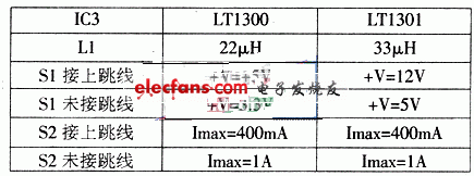
The output voltage and current of the regulator IC3 depend on the selected model (LT1300 or LT1301) and the configuration of the jumper interfaces S1 and S2. For instance, with S1 connected to the jumper, the circuit provides a DC voltage output of +5V (using LT1300) or +12V (using LT1301). When S1 is not connected to the jumper, outputs of +3.3V (LT1300) or +5V (LT1301) can be achieved. Similarly, the status of S2's jumper determines whether the output current is 400mA or 1A.
Attached below is an image of the power circuit for your reference. The diagram clearly shows how the components interact to maintain a stable DC voltage supply, even under varying conditions of solar input and battery charging demands.

Optical Fiber Fusion Splicer,Water-Proof Fusion Splicer,Six Motors Fusion Splicer,Fusion Splicer For Trunk Project
Guangdong Tumtec Communication Technology Co., Ltd , https://www.gdtumtec.com