The integration of solar energy for charging the battery to maintain an uninterrupted DC voltage output is one of the key features of this circuit design. The circuit is composed of a constant current charger (IC1), an overcharge protection circuit (IC2 and T1), and a linear switching regulator (IC3).
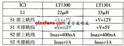
The constant current charger IC1 has a limit of 60mA. When the battery B is overcharged—such as during prolonged exposure to strong sunlight or when the load current is minimal—the battery voltage increases, causing the voltage at the sliding terminal of P1 to rise. The voltage controller IC2 then intervenes by activating T1, which saturates and conducts. This action diverts some or all of the current to ground via resistors R5 and R7, and the LED1 lights up to prevent overcharging. The output voltage and current of the regulator IC3 depend on the selected model (LT1300 or LT1301) and the configuration of the jumper interfaces S1 and S2.
As illustrated in the accompanying table, when S1 is connected to the jumper, you can obtain a DC voltage output of either +5V (using the LT1300) or +12V (using the LT1301). If S1 is not connected to the jumper, the output shifts to +3.3V (LT1300) or +5V (LT1301). Similarly, the status of S2—whether it’s connected or left open—determines whether the output current will be 400mA or 1A.
Below is an image showing the power circuit design for reference:

This circuit ensures efficient energy management while offering flexible voltage and current outputs, making it suitable for various applications requiring stable DC power supply. Additionally, the solar charging feature adds sustainability and reliability, making it ideal for remote or off-grid setups.
4D Laser Level,Laser Level Standard,Wall Mount Laser Level,Multiple Laser Level
Guangdong Tumtec Communication Technology Co., Ltd , https://www.gdtumtec.com