Have you ever faced a situation where, despite using various filtering techniques, there's still a slight overshoot during EMI testing? This article introduces effective methods that can help you pass EMI tests more easily or simplify your filter design. The technique involves modulating the power switching frequency to introduce sideband energy, transforming narrowband noise into wideband noise. While this doesn't reduce the total EMI energy, it redistributes it, effectively lowering harmonic peaks.
In the case of sinusoidal modulation, two key parameters can be adjusted: the modulation frequency (fm) and the change in the switching frequency (Δf). The modulation index (B) is defined as the ratio between these two values:
**B = Δf / fm**
Figure 1 illustrates how changing the modulation index affects the EMI spectrum. When B = 0, there is no frequency deviation, and only a single line appears. As B increases to 1, the signal’s frequency characteristics begin to broaden, with the central frequency component dropping by about 20%. At B = 2, the spectrum spreads even further, and the peak at B = 0 decreases by 60%. Using frequency modulation theory, we can estimate the energy distribution in the spectrum. According to Carson’s Law, most of the energy lies within the bandwidth of 2*(Δf + fm).
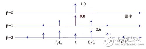
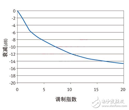
Figure 2 shows the effect of a larger modulation index, demonstrating that peak EMI can be reduced by over 12 dB.
Choosing the right modulation frequency and frequency offset is crucial. The modulation frequency should be higher than the EMI receiver’s bandwidth to prevent simultaneous measurement of sidebands. However, if it's too high, the power control loop may not suppress voltage changes effectively, leading to output voltage fluctuations. Additionally, excessive modulation might cause audible noise in the power supply. Therefore, it's common practice to set the modulation frequency outside the audible range but not too far from the receiver bandwidth.
As shown in Figure 2, adjusting the operating frequency upwards is generally preferable. However, this impacts the power supply design, requiring careful selection of magnetic components for the lowest operating frequency. Lower frequencies also mean the output capacitor must handle larger ripple currents.
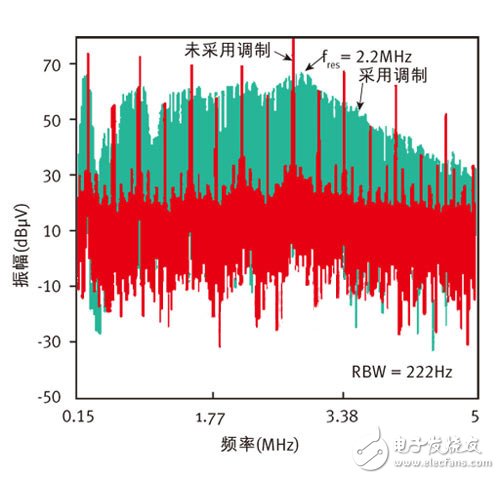
Figure 3 compares EMI performance with and without frequency modulation. Here, the modulation index is 4, and as expected, EMI is reduced by approximately 8 dB relative to the fundamental frequency. The broader harmonics spread across the frequency band, with each harmonic stretching accordingly—such as the third harmonic spreading to three times the fundamental frequency. This broadening process continues at higher frequencies, significantly improving the noise floor compared to fixed-frequency operation.
While this technique isn’t ideal for low-noise systems, many applications can benefit from it. It not only increases the design margin but also greatly reduces the cost of EMI filters.
Optical Mirrors,Concave Spherical Mirrors,Elliptical Flat Mirrors,Silver Optical Mirrors
Danyang Horse Optical Co., Ltd , https://www.dyhorseoptical.com