With the continuous development of integrated technologies, phase-locked loop (PLL)-based silicon chip timing solutions are becoming more common, providing a cleaner, more stable clock selection solution for designs that require multiple frequencies. The purpose of this paper is to discuss in detail the value proposition of using silicon chip timing solutions to solve timing design challenges and compare them to traditional design methods using multiple independent crystal or crystal oscillators (XO).
1. The need to use multiple frequencies in HDTV systems - different standards and interfaces
Figure 1 shows the basic schematic of a liquid crystal television antenna, which briefly illustrates the flow of digital television processing the input digital data stream into a correct audio and video format suitable for use in a television set in the user's living room.
This article refers to the address: http://
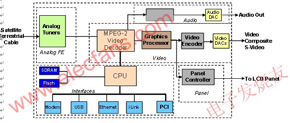
Figure 1: Common LCD TV architecture
Multiple subsystems have been added to the tuning board. The basic functions can be broadly classified into the following modules:
Analog front end (demodulator)
2. Audio/Video Encoding and Decoding (MPEG Video Decoder/MPEG Audio Decoder)
3. Various interfaces
4. Display
Almost all modules shown in the above figure require a clock signal. The typical clock signal required by the CPU is 30 – 100MHz. The MPEG standard requires a 27 MHz based clock input. There is a necessary function that requires synchronization between the decoder and the encoder, and this function is implemented by VCXO (Voltage Controlled Crystal Oscillator). For audio clocks that are clock sources for digital-to-analog converters (DACs), the ppm requirements are extremely stringent. These frequencies depend on the sampling frequency and the oversampling ratio. For various types of interfaces, the clock signals are determined by their respective standards, such as USB, Ethernet, modem, PCI, PCI Express, SATA, and so on.
The display's clock depends on the screen size and display standard (High Definition (HD): 1080i, 1080p, 720p; Standard Definition (SD): NTSC, PAL). The basic system of the screen controller subsystem is to convert the input image data into an actual screen size, for example, using a clock such as 74.17582418 MHz.
2. Implementation of TV architecture and clock tree
Currently, a key decision that designers have to make in the early stages of design is the signal format, including analog or digital signals. A few years ago, the signal link of televisions was based primarily on analog signals, and today, more commonly used are digital audio data paths. Both digital and analog paths have their own inherent advantages and disadvantages. However, there is currently a global inevitable development trend that requires all signal transmissions to adopt digital technology, and this trend will be realized in stages.
High-definition televisions use digital signals, so new TVs tend to use digital channels. The advantage of using digital transmission is that it is highly fault tolerant to noise. On the other hand, analog signals are susceptible to noise. Board designers need to pay special attention to wiring, using differential signals with better signal-to-noise ratio (SNR) performance, or using shielding techniques to avoid signal degradation.
Traditional clock tree design: This approach uses a separate crystal/crystal oscillator (XO) for each frequency requirement. The advantage of this approach is that the clock can be placed very close to the component, making the wiring simple. However, the drawback of this approach is that each crystal/crystal oscillator component must be purchased from the supplier in advance, thus not allowing design changes to be made at the final stage. If there is a change in frequency, a long lead time is required, which leads to a delay in the overall progress.
Silicon Chip Timing Solutions: The popularity of phase-locked loop-based timing solutions has surpassed traditional clocking methods for more than a decade. Silicon chip timing solution vendors can offer multiple functions not supported by discrete crystal and crystal oscillator components for complex system designs. The trade-off between these two design approaches will be discussed below. The main benefit of turning to customers with this architecture is that it gives the customer a design flexibility and cost savings.
3. Advantages of phase-locked-ring silicon chip timing solutions compared to discrete crystal/crystal oscillators
1. Cost – One of the driving factors for important decisions in the consumer market segment is cost. Every change in the architecture must be economical and cost-effective, so that the structural transformation can be implemented and the investment is reasonable. The most attractive advantage of silicon timing solutions is that by integrating several crystal/crystal oscillators, you can reduce overall bill of materials costs, maintain performance levels, or in some cases improve performance levels. In a typical TV antenna board as shown above, 5-6 discrete crystals (costs of 0.12 – $0.50 each) are used, and if a programmable silicon chip clock generator can provide the above frequencies The cost of less than $2.00 will really add value to the board. In addition to cost being the primary driver for crystal/crystal oscillator integration, there are other advantages that can be felt for OEMs and end users.
2. Reliability—The crystal is a quartz-based component that has a higher failure rate than a phase-locked loop-based timing solution. Every reduction in one crystal from the system helps to increase the reliability of the entire system. High integration also reduces the number of components on the board for maximum stability and lower repair rates.
3. Crystal availability - Crystals with a frequency range between 10-40 MHz are easy to do. However, high frequency crystals above 40 MHz are more difficult to manufacture and require special manufacturing techniques. This crystal is a high-order overtone crystal with a cost range of $1 to $1. These high order crystals are more difficult to purchase. The silicon chip timing solution can generate multiple high frequency outputs using a single low frequency crystal (or a clock reference signal can be used).
4. Crystal aging - The crystal itself is prone to aging, and there is an error of +-2ppm to +-5ppm every few years. This aging phenomenon is caused by impurities present inside the crystal material and above the crystal surface as well as mechanical stress between the crystal material and the deposited electrode. Aging can cause a slow decline in system performance using crystals. Long-term frequency drift has become a common problem when using crystals. The phase-locked-based silicon chip timing solution maintains accuracy throughout the life of the product.
5. Programmability – The phase-locked loop-based clock generator has built-in programmability that provides some flexibility during the design phase. These programmable features include not only the change in output frequency, but also the ability to change the drive signal strength setting, the percentage of spread, and the frequency selection via pin programming, which means that the same output can provide different frequencies as needed. The built-in programmability of the system can be used to change some specific parameters during the design execution process using the serial I2C interface. This feature is attractive to manufacturers who use the same set of frequencies on multiple platforms.
6. Reduce component count and save board space - Using a programmable clock generator helps reduce the number of components on the board through integration. System designers are tended to use fewer components to reduce the problems caused by wiring and the need to maintain signal integrity. The phase-locked loop-based clock generator can generate several outputs with a low-frequency crystal, so it is valuable for reducing the total number of components and saving valuable board space.
7. Use spread-spectrum clock to reduce electromagnetic interference - TV antenna circuit board is typically 5-7 layers, and a dedicated paving layer is used to reduce interference. To improve system performance and avoid crosstalk, distortion, and signal integrity issues, multiple high-speed signals are carefully routed. Silicon chip timing device vendors have reduced these board design issues by providing features such as spread spectrum. For example, spread spectrum can reduce the peak energy of the signal by extending the high speed signal.
Electromagnetic interference must be below the limits specified in the mandatory standards such as CISPR 22 or FCC Part 15 Class B. All consumer products must pass the strict FCC certification to be listed. Regulators around the world, such as the United States Communications Commission (FCC), ensure that mandatory standards are adhered to and that device products cannot transmit signals in bands that do not belong to them. Unfortunately, high speed designs with frequency harmonics often encounter this problem. Spread spectrum is a feature currently provided by integrated circuit vendors that can solve this interference problem.
Spread spectrum capabilities reduce or even eliminate the need for ferrite beads, filters, coils, and vibrators that increase bill of materials costs. If the system fails the electromagnetic compliance test, it will take a lot of effort to redesign. Taking into account the cost of the test and the time wasted to re-engineer the project, we will recognize the importance of considering these issues and taking insurance measures, such as the use of spread-spectrum in advance. With programmability, you can turn on the spread spectrum function when you need it and turn it off when you don't need it. This feature is especially useful in development and testing.
8. Inventory Management – ​​One of the main challenges facing the procurement team today is managing the inventory, demand and forecasting of each component used in the system. Since each OEM has multiple product platforms and sub-platforms, these platforms and sub-platforms are in different market segments and are specific to specific target markets, and managing this supply chain is a very arduous task. We can imagine how cumbersome it is to manage 10 crystal products with different frequencies and supplied by different suppliers around the world. Silicon chip timing component vendors offer programmable clock generators that can be solved by designers using software to generate different frequencies during design. This programmability not only makes the designer's job easier, but also provides different frequencies to meet the timing goals, and allows the purchasing team to purchase the same device products from multiple platforms. If the demand for one of the platforms suddenly increases, the procurement team can use the purchased devices that were originally on different platforms. In addition, because there are features such as pin-programmable for frequency selection, these components can be used without significant impact on the design.
9. Perfect Synchronous Output - Some applications may require several clock signal copies and require that these replicated clocks be fully synchronized or consistent. This feature is available through a programmable phase-locked loop device. When using several discrete crystals, achieving such synchronization performance can be difficult.
10. Power Management - A clock based on a programmable phase-locked loop can meet the special needs of the portable device market, including game consoles, smart phones, personal media players, digital cameras, camcorders and more. In these power-sensitive applications, certain frequencies can be selectively turned off by using I2C communication or pin programming techniques. For example, in the smartphone world, not all applications need to run for a long time. This particular frequency can be turned on when the user wishes to use one of the functions, for example, when using the GPS function. Once this feature is no longer used, the system can reduce this frequency source to reduce power operation. This is not easy to achieve in traditional designs using discrete crystal/crystal oscillators.
4. Why do I need to reduce the electromagnetic interference of the LCD panel controller?
LCD screens are now ubiquitous and extremely popular, and their application in our real life is more than we imagined. These include the 3.5-inch touchscreen of all the new iPhones you're buying, the Sharp Aquos® TVs you bought at Thanksgiving Day, or the sparkles you see in the bustling strip of Las Vegas. Street signs, or more commonly, the ThinkPad notebooks you use every day – the technology that powers these visual enjoyments is actually liquid crystal technology. This penetration of LCD panels suggests that the technology that has driven it is already mature, and the price of new models is more reasonable than before.
The demand for LCD screens is also increasing, requiring larger panels, less electromagnetic interference, lower power consumption, and higher image quality.
Here, we take a closer look at the architecture of the LCD panel from a higher level. The liquid crystal panel is actually an array of transistors that modulate the voltage across the liquid crystal and thus control the amount of light that passes through the panel. The color display is essentially achieved by using filters that allow red, green, or blue light to pass through a given pixel. The row driver is connected to the gate of the transistor. The row driver controls which row of pixels is being programmed at any given time by applying an "on" or "off" voltage. The sources of these transistors are connected to the column drivers, while the column drivers supply the specific voltage required to achieve the correct pixel brightness.
The timing controller takes display data from the host and transfers the data to the column and row drivers through the panel interface. Additional functions such as overdrive to reduce motion blur, enhance images, and gamma correction can also be added. The row driver interface uses a transistor logic circuit (TTL) as the signal generation stage. The column driver interface requires a lot of bandwidth for a clearer display, so a different bus architecture is used—typically with Swing Differential Signaling (RSDS).
LVDS Transmitter LVDS (Low Voltage Differential Signaling) Transmitter
Ref Clock reference clock
SS Clock Spread Spectrum Clock
LVDS ReceiverLVDS Receiver
Timing Controller Timing Controller
Color Processing Color Processing
RSDS TransmitterRSDS Transmitter
Row Driver line driver
Column Driver column driver
LCD Panel LCD panel
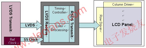
Figure 2: LCD panel controller block diagram
One of the main challenges in panel electronics is to reduce interference to meet electromagnetic compatibility (EMC) specifications. Panel manufacturers typically offer different types of panels for different types of applications, including televisions, PC monitors, laptops, handheld devices, personal entertainment systems, and more. But panel makers tend to use the same board on all sizes of panels. But how do these manufacturers use a two-layer circuit board with a limited size to meet the electromagnetic interference (EMI) test requirements? How effectively do they design printed circuit boards (PCBs) for various screen sizes, and can they complete projects on time while meeting electromagnetic specifications?
There are several ways to achieve these goals. One is to improve the quality of printed circuit board materials and to add additional circuit board layers that use dedicated flooring. Printed circuit boards in most LCD panels are manufactured using standard FR4 materials. Taking into account the increased cost, using more expensive printed circuit board materials and adding more board layers is not a viable option. Another way to reduce electromagnetic interference is to use filtering, but this method is not a perfect solution for all panel sizes. Moreover, every circuit network needs to be filtered. Failure to meet electromagnetic compatibility test requirements can result in re-engineering and impact on the product's time to market.
As shown in Figure 2, spread spectrum (SS) clock generators have become a popular way to solve the electromagnetic interference problem. A number of silicon integrated circuit suppliers, including Cypress Semiconductor, have been able to supply spread-spectrum clocking products for liquid crystal display systems. The advantage is that it can solve the electromagnetic interference problem in the early stage by a systematic method. The spread spectrum function can be selectively turned on, and the spread percentage can be adjusted to obtain a suitable amount of expansion for electromagnetic compatibility testing. For different size panels, the percentage of expansion can also be different, which can be determined as needed, and the components used are the same. Due to the limited space of the boards, these clock products are available in very small package sizes.
In general, the architecture of digital television, including LCD TVs, is evolving and is adopting newer methods to deliver high-quality "high-definition" levels of audio and video while maintaining economic legitimacy for the final market. Digital TV manufacturers are increasingly recognizing the value of silicon chip multi-phase-locked loop and spread-spectrum clocking methods in improving performance and speeding time-to-market.
LED to shoot the light, English name is LED spotlights, it is the most popular energy conservation and environmental protection products, with more and more of lamps and lanterns made of LED as light source, one of the most acclaimed is LED to shoot the light, as compared with other LED lamps, LED lamp price is lower.LED lamp is mainly used for decoration, commercial space, lighting and Building Lighting, etc., with the development and progress of LED technology, the market of LED lamp performance advantage is very outstanding, high purity aluminum reflector, the beam is the most accurate and reflective effect is best;Symmetrical light distribution systems such as narrow Angle, wide Angle and asymmetric etc., and the projector lamp is equipped with a scale plate, people can adjust the radiation Angle conveniently according to the scale.In addition, in order to facilitate maintenance, the LED projector lamp is replaced by a back-up switch.The lighting decoration effect is first-rate, and the LED projection lamp can realize the dynamic effects of gradual change, jumping, color flashing, random flashing, gradual change, chase and scanning.

1. LED spotlights can be driven by low-voltage direct current: it has the advantages of small load and weak interference, and has low requirements on the use environment.2. LED spotlights can control the composition of the luminous spectrum well, so that they can be well used for local or key lighting in museums and exhibition halls.
3. The luminous directivity of LED spotlights is very strong: the luminance attenuation is much lower than that of traditional light sources, and the price of LED spotlights is fairly civilian.
4. The response time of LED spotlights is very fast: at the microsecond level, as long as the switch is on, it will be on immediately without any delay or flicker.
5. The light energy concentration of LED spotlights is very high: it is concentrated in a small wavelength window with high purity.
6. The service life is very long, generally between 50,000 and 100,000 hours, because LED is a semiconductor device, and even frequent switching will not affect the service life.
7. Good environmental protection, LED to shoot the light in the process of production don't add "mercury", also do not need air, do not need glass shell, good impact resistance, good shock resistance, invulnerability to breakage and facilitate transportation, very green, known as "green energy", the LED lamp price.
8. Energy saving, the spectrum of LED spotlights is almost all concentrated in the visible light frequency band, and its luminous efficiency can reach 80 ~ 90%.It is generally believed that the energy-saving of energy-saving lamps 4/5 is a great innovation, but LED spotlights are more than 1/2 energy efficient than energy-saving lamps, which is a greater reform of solid light sources.
Led Spot Light Series,Led Track Spot Light,Mini Led Spot Light,Led Spot Light
Jiangsu chengxu Electric Group Co., Ltd , http://www.satislighting.com