TI's DAC34H84 is a 4-channel, 16-bit, 1250 Msps DAC. The reason for this is that it is a typical high-speed digital-to-analog converter with an input FIFO with isolated input and DAC clock domain, an interpolated digital block, fine frequency resolution digital quadrature modulation, analog quadrature modulator correction, and sin (x)/x correction (see Figure 1). This article will introduce the functions and functions of these features one by one.
The first digital block is the interpolation module, which is responsible for increasing the sampling rate of the digital signals inside the DAC. In general, interpolation is achieved using a double sampling rate increase step. This is done by inserting zeros between the input sample points, which produce two signals at fIF and FIN – fIF. After passing through a digital low-pass filter, the second signal at FIN – fIF is removed and only the signal is left at fIF. The reason for using interpolation is related to the zero-order hold output structure used by most high speed DACs. With zero-order hold, the DAC sets the output amplitude accordingly based on the digital samples at the beginning of the clock cycle and then holds it until the end of the clock cycle and the next output sample. This produces an "upstairs" output whose frequency response is expressed as Equation 1:
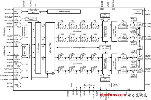
Figure 1 DAC34H84 functional structure diagram
Where fIF is the analog output frequency and fs is the sample rate. This response has a low-pass effect (see Figure 2) with a loss of ~ 3.5 dB at f = fs/2 and zero at fs multiples. Although the DAC output has a signal image at N*fs +/- fIF, the image amplitude in the higher Nyquist region is much lower than the signal at fIF, resulting in a lower signal-to-noise ratio (SNR). And there may be a significant amplitude drop. This limits most applications to output signal frequencies below fs/2. In addition, the spacing between the signal at fIF and the fs – fIF image decreases as fIF approaches fs/2, making it difficult to establish an analog filter at the DAC output (which removes fs – fIF unwanted images) and will eventually The fIF for most applications is limited to below fs/3.
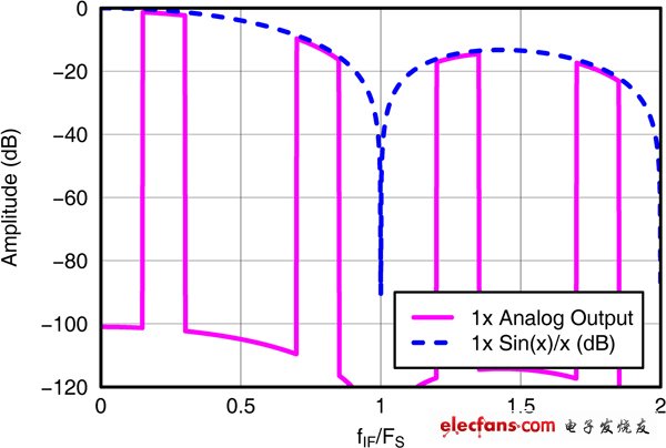
Figure 2 DAC output spectrum without interpolation module
Use the DAC Interpolation Module to increase the internal DAC sampling rate by simply making the DAC's digital interface rate, fIN, high enough to allow signal bandwidth transmission, and with a small additional amount of bandwidth to have the interpolation filter transition band (real signal timing) 2.5*BW, when complex signal, fin > 1.25*BW). Using interpolation to increase the sample rate allows the signal to easily lie below fs/2.
Another benefit of increasing the sample rate is that digital mixing can increase the output IF to higher frequencies. For example, with 2X interpolation, the output frequency can be higher than fin/2, which is not possible without interpolation (see Figure 3). In general, complex input signals use a complex mixer to avoid image generation during mixing. The mixed output can be either a real IF signal or a complex IF signal, valid after the analog IQ modulator DAC.
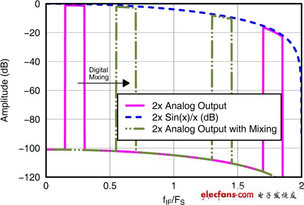
Figure 3 2X Interpolated DAC Output Spectrum
Using the complex DAC output for an analog quadrature modulator (AQM) highlights another useful digital feature common to high-speed DACs—the quadrature modulator correction block. This module is responsible for correcting the gain, phase, and offset imbalance of the analog quadrature modulator to improve AQM sideband rejection and LO feedthrough.
Finally, at the end of the digital signal chain is a digital FIR filter that compensates for the Sin(x)/x high and low frequency regularity attenuation of the first Nyquist zone. In the DAC34H84 implementation, the filter can provide compensation up to 0.4*fDAC with an error of less than 0.03dB.
As described in this article, high-speed DACs such as the DAC34H84 have a large number of digital features. These features make system implementation simple and easy by reducing data rates and improving output signal characteristics.
An anti-theft system is any device or method used to prevent or deter the unauthorized appropriation of items considered valuable. Theft is one of the most common and oldest criminal behaviors specially happened popularly at Telecom base site and power station from ASEAN, Africa and Asia, etc. Our anti-theft systems via GPS tracking management technology have been evolved to match the introduction of new inventions to stationary batteries and the resulting thief been caught as soon as stealing the batteries.
At present, there are huge number of Telecom base stations all over the world, the vast majority of sites are located in remote areas with any unattended which are stolen seriously. Theft violently destroy the infrastructure of the base station and steal batteries, resulting in serious losses such as communication breaking and stations maintenance. The conventional protective measures, such as iron guardrail, external positioning alarm device, and anti-theft screw, not only are unable to achieve your desired effect, but also have the disadvantages of higher cost, lower battery life and weaker concealment.
Our battery anti-theft solution and Monitoring Tracing system is comprised of GPS module and software operation platform. This equipment includes GPS satellite positioning system and network positioning system, that is GPS+LBS dual intelligent positioning mode. It has the function of satellite positioning, base station locating, remote reset, remote upgrade, fence alarm, tracking replay, battery low voltage alarm, vibration alarm,etc.
The utility model aims at resolving the problem that an Uninterrupted Power Supply (UPS) storage battery of a field station can not guard against a thief effectively and providing a global position system (GPS) and anti-theft monitoring tracing system for a storage battery. A terminal module is connected with a management platform and mobile phone signals through a mobile communication network. The terminal module comprise a GPS module, a central processing unit (CPU) module connected with a mobile communication network module and a vibration transducer connected with the CPU module.
Battery GPS Anti-Theft System,Battery GPS Tracker,Car Truck GPS,Battery Anti Theft Controller
Shenzhen Daceen Technology Co., Ltd. , https://www.daceen-sz.com