introduction
This article refers to the address: http://
This paper implements a part of the vehicle information collection system on the embedded Linux platform—the data collection of the vehicle's normal temperature, such as collecting the temperature inside the car, the temperature of the heater or the air conditioner, the temperature outside the car, and the temperature of the water tank. The DS18B20 is a network-configurable single-bus digital temperature sensor that provides a cost-effective solution for information acquisition. Embedded Linux has become a system platform widely used in in-vehicle devices due to its excellent open source code, easy customization and expansion, multi-hardware platform support and built-in network functions. The system involved in this article uses Samsung's S3C2410AL20 processor, the operating system uses 2.6.8.1 kernel Linux, and the GUI uses Trolltech's Qtopia. The main functions are: collection and display of temperature, audio alarm, temperature data storage, and related functions. Settings, etc. When a voice prompt or alarm is required, the application calls the voice module; when it is necessary to store or display historical data, the application calls the SD storage module.
1 Overview of Linux System Development
Driver development is one of the main tasks of embedded Linux development. The device driver provides the device interface for the upper-layer application to control the hardware, while directly dealing with the Linux kernel. Figure 1 depicts the Linux system development framework.
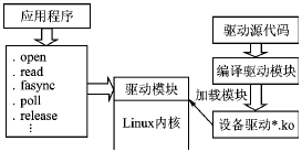
Figure 1 Linux system development framework
Application development is another major task in embedded Linux development. Qt/Embedded is a Qt version for embedded systems developed by the famous Qt library developer Trolltech. Based on the Qt/Embedient Library, Qtopia is an open source application package and development library for mobile devices and handheld devices running embedded Linux such as PDA and SmartPhone. It includes a full set of personal information management PIM (Personal Information Management), such as address book, schedule, MPEG playback, image display, browser and so on.
2 Overview of vehicle information systems and hardware platforms
The development of vehicle information acquisition system mainly includes user interface development, kernel development, audio module design, serial port module design, CAN bus module design, vehicle status (including switch quantity, analog quantity, digital quantity, etc.) detection module design.
This design focuses on data acquisition for one-wire temperature networks. The temperature signal characteristics of the one-wire temperature network are: the value is not high, mostly in the range of 0~100 °C; the temperature signal changes slowly; the real-time requirement of the collected temperature signal is not high; the accuracy requirement is not high.
The advantage of a first-line network is that it can measure a large amount of physical quantities, all of which pass through a one-line protocol, regardless of the specific amount being measured. The first-line network is a network that can easily set up a series of measurement environment parameters composed of one-line sensor chips.
The DS18B20 is a networkable single-bus digital temperature sensor with the following features:
1 Adapts to a wide voltage range (3.0 to 5.5 V) and can be powered by the data line in parasitic power mode.
2 Unique single-wire interface mode, the DS18B20 only needs one port line when connecting with the microprocessor to realize the two-way communication between the microprocessor and the DS18B20.
3 The temperature range is -55 to +125 °C, and the accuracy is ±0.5 °C at -10 to +85 °C.
4 Programmable resolution is 9 to 12 bits, and the corresponding resolvable temperatures are 0.5 °C, 0.25 °C, 0.125 °C and 0.062 5 °C, which can achieve high precision temperature measurement.
A single bus makes hardware overhead extremely small, but requires relatively complex software to compensate. Because the DS18B20 uses single-bus serial data transfer, ensuring strict read and write timing becomes the key to temperature measurement. Therefore, instead of using I/O drivers, a one-wire temperature network driver is written separately.
This design uses a parasitic power connection with 12-bit resolution. The advantages of parasitic power supply are: remote temperature detection does not require a local power supply; ROM can also be read in the absence of normal power conditions. To ensure that the DS18B20 receives sufficient supply current during its active conversion period, a strong pull-up is provided through the MOSFET on the I/O line (see Figure 2). When using parasitic power mode, the VDD pin must be tied to ground.
The system core controller S3C2410X is Samsung's ARM920T core based chip. The S3C2410X integrates an LCD controller (supports STN and TFT LCD screens with touch screen), SDRAM, touch screen, USB, SPI, SD and MMC controllers, 4 PWM-enabled timers and 1 internal clock. , 8-channel 10-bit ADC, 117-bit general purpose I/O port and 24-bit external interrupt source, 8-channel 10-bit AD controller, processor operating frequency up to 203 MHz. The system displays a TFT_LCD LCD with a SHARP 3.5 in. The system block diagram is shown in Figure 2.
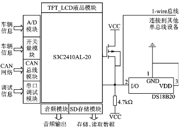
Figure 2 Information acquisition system and part of the circuit connection principle
3 driver implementation
This section will implement the drive module for the one-wire temperature sensor network. The driver is generally divided into two parts: the driver and kernel interface layer, and the hardware device interface layer.
3.1 driver and kernel interface layer
The driver and kernel interface layer mainly completes the registration loading and uninstalling of the driver module in the Linux kernel. This part of the work is done by the initialization and exit functions, respectively.
1 initialization function to complete the driver module loading:
Static int __init DS18B20_init(void){
......
Register_chrdev(DS18B20_MAJOR, DEVICE_NAME, &DS18B20_fops);//Complete device registration
#ifdefCONFIG_DEVFS_FS//Create device file system
Devfs_mk_cdev(MKDEV(DS18B20_MAJOR,0),S_IFCHR | S_IRUSR | S_IWUSR | S_IRGRP,DEVICE_NAME);
#endif
......
}
2 Exit function to complete the driver module uninstall:
Static void __exit DS18B20_exit(void) {
#ifdef CONFIG_DEVFS_FS
Devfs_remove(DEVICE_NAME);//Remove device files
#endif
Unregister_chrdev(DS18B20_MAJOR, DEVICE_NAME); //Complete device logout...
}
3.2 hardware device interface layer
The hardware device interface layer is used to describe the interaction of the driver with the device. This work is done through the interface between the virtual file system and the device driver. This interface is defined by the file_operation structure, which has the following structure:
Static struct file_operations DS18B20_fops ={
.owner=THIS_MODULE, //point to the module that owns the structure, the kernel uses the structure to maintain module usage counts
.open=DS18B20_open, //Open the device function
.read=DS18B20_read, //Read interface function
.write=DS18B20_write, / / ​​write interface function
.fasync=DS18B20_fasync, //Asynchronous notification function
.poll=DS18B20_poll, //poll function
.release=DS18B20_release, //release device function
};
3.2.1 Opening device functions
Opening the device function mainly completes the initialization of the device.
DS18B20_open(struct inode *inode,struct file *filp) {
Initial_Timer ( ); / / initialize the timer, so that the kernel module reads the temperature according to a certain period
Initial_Device_DS18B20();//Initialize hardware
Readtemperature();//Start reading...
}
Void readtemperature(void) {
...Temperature=DS18B20read();//Read two 8-bit data, the hardware operation timing completed by this function, the current channel is specified by the current read channel number variable.
DS_SLOT_NO () ;/ / put this read channel number into the buffer
DS18B20Event();//Data is put into the buffer, wake up the wait queue and start asynchronous notification
If(ReleaseFlag)
CycleTimer_Delay_Soft(hdelay);//If the stop signal is not read, the kernel timer is delayed, the next read is performed, and the read is started again in the interrupt service routine...
}
Before using the kernel timer, you need to define a timer structure static struct timer_list CycleTimer. The following are the specific operations of the timer:
Static void Initial_Timer(void) {
Init_timer(&CycleTimer); );//Initialize timer structure
CycleTimer.function=DS18B20_timer; //Hook timer interrupt service routine
}
3.2.2 Reading Interface Functions
When the user program performs a read operation, there may be no data that can be read. In this case, the read operation needs to wait until there is data to be read. Here, the wait queue is used to make the process wait for no data to be read, and wake up when the data arrives. The wait queue is set to a circular buffer, each time a new data is placed as the head of the buffer, and the data that has been stored for the longest time has not been taken is the end of the buffer.
DS18B20_read( ) {
DECLARE_WAITQUEUE(wait,current);//Declare a wait queue...
Next_try:
If(DS18B20dev.head != DS18B20dev.tail) {//Wait queue is not empty, that is, there is data
DS18B20_ret=Read_Buffer_DS18B20(); // Take the tail of the buffer
Copy_to_user( ); //Read data is sent to user space
}
Else { ......//wait queue is empty, ie no data
Add_wait_queue(&queue,&wait);
Current>state=TASK_INTERRUPTIBLE;//Add a wait queue, declare the status as a task interruptible
While((DS18B20dev.head==DS18B20dev.tail)&&!signal_pending(current) {//Enter waiting
Schedule();
Current>state=TASK_INTERRUPTIBLE;
}//If the buffer is empty, the Linux kernel schedules, waiting for notification
Current>state = TASK_RUNNING;//Get notification of data, declare the task status as running
Remove_wait_queue(&queue,&wait);//delete wait queue
Goto Next_try; / / return to read data
}
}
3.2.3 fasync asynchronous notification function
The asynchronous notification function sends a SIGIO signal to the process to notify the process of accessing the device, indicating that the device is ready for I/O reading and writing, avoiding active query and improving program efficiency. To use asynchronous notifications, add a structure pointer to the struct fasync_struct and then implement the fasync interface function.
Static struct fasync_struct *fasync;//Define a structure
Static int DS18B20_fasync(int fd,struct file *filp,int on) {//Implement interface function
Retval = fasync_helper(fd,filp,on,&fasync);
If ( retval<0) return retval;return 0;
}
Finally, the kernel's kill_fasync function is called where it needs to be notified to the user space. The DS18B20Event() function mentioned in the Open Device function is: put data into the circular buffer, wake up the wait queue and start asynchronous notification, the latter two functions are implemented like this:
Wake_up_interruptible(&queue);//Wake up wait queue
If (fasync) {
Kill_fasync(&fasync,SIGIO,POLL_IN);//Send asynchronous notification signal
}
3.2.4 poll system call operation interface function
When a program needs to read and write to multiple files, if a file is not ready, the system will be in a state of read-write blocking, affecting the reading and writing of other files. To avoid read and write blocking, use the poll function. If the device reads without blocking, it returns POLLIN; the usual data is ready to be read and returns to POLRRDNORM.
Static unsigned int DS18B20_poll(struct file *flip, poll_table *wait) {
Poll_wait(flip,&queue,wait);
If(DS18B20dev.head != DS18B20dev.tail) {
Return POLLIN|POLLRDNORM;
}
Return 0;
}
3.2.5 release release device function
Static intDS18B20_release(struct inode *inode,struct file *filp) {
ReleaseFlag=0//The kernel stops reading the temperature flag
DS18B20_fasync(1,filp,0);//Close asynchronous notification
Module_put(THIS_MODULE);//Device counter minus 1
Return 0;
}
The write interface function is used to notify the driver. For example, the notification driver reads the data of channel 2, and executes the write interface function write(fileno, &SLOT2, 1) in the application, and the driver sets the current read channel number to 2.
This completes the driver interface function. This driver is a character device driver and places the source program under the driver/char directory. Also need to modify the Kconfig configuration file in this directory and add Config 18B20_S3C2410 option, modify driver / char / Makefile, add obj $ (CONFIG_18B20_S3C2410) += S3C2410_18B20.O. Finally reconfigure the kernel and add the driver to the kernel as a module so that you can compile the driver.
4 Qtopia application design
(1) Creating a project
First create a form application, Thermometer Figure.ui, using the QT Designer designer. After the form program is created, add form controls, slot functions, signals, etc. as needed. Figure 3 is a block diagram of the implementation of the Thermometer Figure class.
(2) ThermometerFigure class implementation
Use the uic tool to generate the corresponding *.cpp and *.h files (implementation files and header files for the form class). Edit the *.cpp and *.h files to implement the connection of each member function and signal slot. The specific implementation is shown in Figure 3.
(3) create main and initialize
First create the main.cpp file and create a QApplication object in main.cpp. The QApplication class is responsible for the control flow and main settings of the image user interface application, processing and scheduling all events from the system and other source files; and including the initialization and termination of the application.
Int main( int argc, char **argv ) {
QApplication app(argc,argv);
ThemometerFigure wyc; / / create objects
app.setMainWidget( &wyc );//Select the main form
Wyc.show(); return app.exec();
}
(4) Edit the *.pro file and generate the Makefile
Use the progen tool to create Thermometer.pro, as follows:
TEMPLATE=app
CONFIG=qt warn_on release
HEADERS=ThermometerFigure.h
SOURCES=ThermometerFigure.cpp \ main.cpp
INTERFACES=
Execute the qmake command to generate the Makefile. Set the relevant environment variables, compiler paths, etc. before execution.
Qmakeo Makefile Thermometer.pro
(5) Compile link project
Executing the make command will generate the target binary Thermometer, which will run on the device.
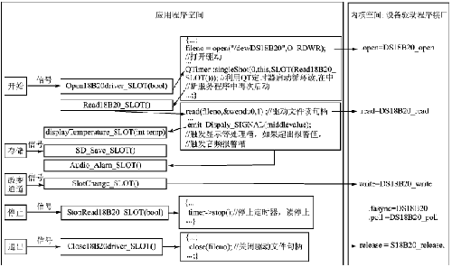
Figure 3 Block diagram of the implementation of the ThermometerFigure class
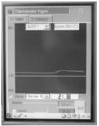
Figure 4 ThermometerFigure class implementation interface
(6) Publish the executable file to the Linux system
Add the executable file to Qtopia's root file system and burn the generated new root file system to the Flash root file system area of ​​the device so that you can run the program on the desktop. Figure 4 shows the implementation of the Thermometer Figure class.
Conclusion
This paper introduces some implementation methods of vehicle information system development. The development process of Linux is described by examples, including driver development and application development process. The innovation lies in the introduction of the first-line sensor network into the vehicle information collection system, which greatly simplifies the line structure and has high practical value.
Power Skiving,Skived Heatsink,Aluminum Heat Sink,Skived Fin Heat Sink
Dongguan Formal Precision Metal Parts Co,. Ltd , https://www.formalmetal.com