One way to achieve the above requirements is to use redundant design within the board in critical areas of the system design. Although this concept is not novel, how to deal with this problem on the T3, E3 or STS-1 network interface is the key to this article. Previously, because the number of ports was relatively small, the redundant design of the network interface was not important. When redundancy is required, there are multiple ways to switch circuits into and out of the network. But as the demand for bandwidth increases, the number of ports and the need for redundancy in the design also increase. This article will introduce several different types of redundancy protection schemes for T3 / E3 / STS-1 network interfaces, especially how to use Maxim T3 / E3 / STS-1 linear interface unit (LIU) or DS315x series devices (DS3151 , DS3152, DS3153 and DS3154) to implement the protection scheme.
Redundancy scheme type 1: 1 protection Whether you are designing a network router, WAN access, DSLAM, T / E ATM upstream or multiplexer, the equipment needs to be able to function normally throughout the entire life cycle of the product, so it is necessary Consider using a redundant solution. There are several ways to achieve this goal. For cases with a small number of ports, relays are often used as an effective solution. Figure 1 shows this type of protection scheme. Please note that line cards are used in the design. When there is a problem with the main card, you can switch to the protection card to replace the main card, and the service from the network will not be interrupted for a long time. In this protection scheme, the line cards are all the same, which is important when maintaining the inventory of replacement cards. The trace connecting the line card 1 and the line card 2 must be as short as possible, so as to prevent the pulse template mismatch caused by the reflection of the transmitted signal. It is recommended that the trace length between the LIU and the BNC connector not exceed 5 inches.
figure 1.
1: 4 protection When the number of line cards exceeds 2, it becomes more difficult to effectively protect the network interface with redundancy. Sometimes a matrix card is used to switch different line cards into the communication network. Although this method is effective, problems can occur when the matrix card fails. In order to replace the card, the system needs to be offline to repair or replace the board.
Maxim has completed a redundancy scheme that allows users to switch line cards while still maintaining the protection card's normal operation. In Figure 2, all line cards have active devices such as the DS315x line interface unit as well as relays and local oscillators. In this design, we did not use the matrix card to switch the signal between the main card and the protection card. On the contrary, we designed a BALUN that is a balanced to unbalanced network scheme, which can also be called a power splitter / combiner. The splitter is a passive device that can distribute the received input signal into multiple outputs with specific phase and amplitude characteristics. As you can see in Figure 2: The power splitter / combiner connecting two separate line cards is directly in front of the BNC connector, one output of the power splitter is connected to the main card, and the other is connected to the card below the main card Up — but not the LIU of the next card, it is connected to the protection bus as we know it. When the line card N is faulty, the relay on the line card N + 1 protection bus is closed and the protection card starts to work, so the data can still be transmitted to the T3 / E3 / STS-1 network. The failed line card N can be replaced without interrupting service.
Figure 2. Power splitter For all T3 / E3 / STS-1 network applications, the output signal of the power splitter should be of equal amplitude, any two signals are in phase, the output signals are highly isolated, and the maximum input to output is 3.0dB insertion loss. When it exceeds 3.0dB, the pulse mask cannot be matched, which is an important condition in all telecommunication applications.
Figure 3 shows a symbolic representation of a common "T" type power divider. Note that this device is a transformer with a center tap as the input, and a resistor is connected across the other two ends. Both ends can be used as output, and in some cases can also be used as two inputs. The resistance across the transformer is the key to this design performance. It helps balance the impedance between port A and port B, while also completely isolating these two ports from input port C.
image 3.
When this device is used as a power divider on the receiving side of Rx or LIU, assuming that the load of port A and port B are exactly the same, the signal is isolated, and the voltage generated at the port will have the same amplitude and polarity. Because the two ports have the same voltage, no current flows through the resistor, and the two ports are completely isolated. Figure 4 shows a graphical description of this circuit. This symmetrical structure shows that I1 and I2 are the same. Therefore, the voltages at point A and point B are also equal.
Figure 4.
When this device works on the transmit side of LIU as a power combiner, it still has high isolation between A and B like a splitter. The signal current from port A flows through the inductor, causing a 180 ° phase change at port B. However, there is no phase change when the current flowing through the resistor reaches port B. Therefore, if RINT selects a specific impedance value, we can ensure that this current is inversely proportional to the current from the inductor. In this case, there is no voltage change at port B, thus achieving a high degree of isolation between the two ports.
For any given T3, E3, or STS-1 network, what should be the RINT value to ensure 100% isolation between Port A and Port B? The power divider / combiner network is redrawn in Figure 5. In this case, in order to obtain a specific voltage at port C, a current flows at port B. The following equation will calculate how to get the isolation with the correct RINT resistance value to get 0V at port A.
Figure 5.
To simplify the equation, we can assume that V1 is 1V, R = 75Ω, and I3 = I4. Since the transformer's mutual inductance is very large, no leakage current will be generated between the two terminals. So we can get the following equation:


Replace I1 with Equation 3 to get RINT's solution. The result is as in Equation 7.
Replace I2 and I4 with Equation 2 and Equation 6, and then replace I5 with Equation 4 to get Equation 8.
Substitute Equation 1 for V3 to get Equation 9.
If you want V2 to be 0V as described above, you can conclude that RINT is 150Ω. Due to the voltage at V1, any other value of RINT will cause a voltage at V2. With RINT of 150Ω, the required isolation between the two ports can be achieved. Please note that due to Equation 1, there is a 1/2 attenuation of the voltage at V3, which may result in failure to match the pulse mask specification of the telecommunications network interface. In order to overcome the voltage drop at port C (V3), DS315x LIU can increase the gain for each transmit port through a test register, the register address is [nx (0 x 10) + (0 x 8)], where n is from 0 To port number 3.
Figure 6 shows the DS315x LIU pulse template, which is configured as 1 x 4 redundant protection according to the structure of Figure 3. After the test register is enabled, even considering the additional load from the power divider / combiner, the DS315x LIU can easily output the voltage required by the E3 pulse mask specification. The schematic and BOM list of this design are available on Maxim's website.
Image 6.
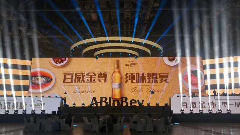
Outdoor Rental LED Screen description: in order to meet the requirements of all-weather performance and performance rental, outdoor LED mobile rental screen is particularly important. Its appearance makes up for the requirements that indoor LED mobile rental screen cannot achieve. Also compared with the traditional outdoor scenery, the grade is not high enough, the display content is single, affected by the environment, the wind is easy to deform, the heat is easy to change color and so on. Outdoor LED rental screen completely makes up for the shortage of traditional scenery.

Outdoor Mobile LED Display features:
1. The brightness is high. In outdoor mobile performance, the brightness is required to be more than 5000cd, otherwise the screen can not be seen clearly due to the influence of sunlight. The brightness of our outdoor performance screen is above 5000cd, which can be used all day.
2. It has strong UV resistance. It can be used outdoors for a long time due to the influence of sunlight. The lamp beads do not fade, but the color is still bright and the light is slow.
3. Outdoor LED mobile rental screen, with rain proof and dust-proof grade up to IP65, rain and wind are unimpeded, and rain proof cloth is used to prevent weather and rain.
4. The cabinet body adopts die-casting aluminum box structure, with good heat dissipation performance and high levelness.
5. For large-scale outdoor performance activities, the screen body can be shaped to form the same picture and split screen picture. For example, part of the screen shows the live content of the stage personnel, part of the screen shows the live broadcast of the audience, etc.
6. Brightness adjustment: according to the requirements of the use scene, the brightness can be adjusted, which greatly meets the requirements of different occasions. We are making perfect use of it both indoors and outdoors.

Outdoor Mobile Led Display Screen structure: quick lock structure, quick disassembly. The air plug and super-v network cable between the boxes can quickly link the signals and power supply between the boxes. The box has a waterproof rubber strip structure, which is waterproof up to IP65.
Precautions: as for indoor screen, pay attention to corners during handling and disassembly, handle with care, and cover the back cover for outdoor use to avoid water flow.
Outdoor Rental LED Screen
LED Display Rental,Rental Stage Led Display,Advertising Led Display,LED Video Screen For Rental
Shenzhen Vision Display Technology Co,.LTD , https://www.ledvdi.com