I. Introduction:
With the deepening of reform and opening up, the number of residents ’cars in our country is constantly increasing, and the growing car wash industry is blowing up the emergence of a new generation of car wash machines. Under this situation, we have recently developed and developed an intelligent -Type steam car washing machine, which uses high-efficiency adjustable piezoelectric boiler heating, generates high-pressure steam to quickly remove dust and oil stains on various automobiles, machinery, electrical appliances and various parts. It has many functions such as automatic pumping and pressure adjustment, and the effect is extremely significant. The unique electrical design makes the water fully atomized, the gas volume is large, but the water consumption is small. The water-saving effect can reach 98%. At the same time, after adding a small amount of disinfectant, it can spray and cover any part of the vehicle, which can play a role in sterilization and disinfection. It is a major auto repair plant, car wash shop, supermarket, residential parking lot, etc. A rare good helper.
2. Introduction of design scheme:
1. The structure of the new steam car washing machine circuit is an electronic product developed using high-performance anti-interference single-chip technology. Its hardware does not require debugging, the software is stable and reliable, and it is easy to use in various harsh environments. It is mainly composed of power supply, main control board, handle, water pump, water inlet and outlet pipes, steam generator, water collection tank, wiper, housing, etc. When the power is turned on, the water pump draws water through the water inlet pipe and sends it to the sprinkler head. The sprinkler head sprays water to the electric evaporator to generate water vapor. High-pressure water vapor is sprayed from the jet head to rinse the dirt. The washed water vapor is The holes in the shell wall are sprayed out of the machine, enter the outlet pipe and condense into water; the water collection groove provided on the inner wall of the shell is used to collect the condensed water on the inner wall and flow out along the outlet pipe, and the bottom wiper of the shell is close to the wiped By moving the steam car washer to make the wiper wipe the object. The machine is also equipped with automatic alarms for water shortage and overpressure; high voltage automatic power off; overpressure automatic exhaust and other multiple safety devices to ensure safe and reliable use.
2. The basic principle of steam car washing After the water is heated to become steam, then 165 ℃ steam is sprayed from the nozzle, then the steam contains a certain amount of heat energy, the temperature of the car body surface is lower than the temperature of the steam, steam car washing The surface of the car body is quickly condensed into water, and the steam releases condensation heat during the condensation process. The condensation heat acts on the dirt layer on the body surface, softens the dirt layer by heat, and is decomposed by the special body cleaning agent and subsequent steam injection under pressure It is very easy to remove. 
3. Circuit hardware:
â‘ Block diagram The local circuit mainly uses STC89RC52 MCU as the core to build the entire circuit. The performance of this MCU is excellent and it has strong anti-interference performance. It can work in its harsh environment and work stably and reliably. Its block diagram is shown in Figure 1. It consists of the following parts of the circuit, including: power circuit, water level and liquid level detection circuit, car wash liquid and glass liquid detection circuit, pressure and steam level detection circuit, flameout detection and coal gas alarm detection circuit, fan water pump detection circuit, coal Steam valve drive circuit, fan and water pump drive circuit, ignition drive and sound drive circuit, and various types of acousto-optical indicating circuits, etc.
â‘¡Working principle: the gas ignition pin detection circuit composed of N5 transistors, through which it controls pin 1 of the single chip, and pin 14 is connected to the light-emitting diode for glass liquid detection. When the glass liquid is detected, the light-emitting diode is blocked. Lit, pin 18-19 is connected to the crystal oscillator, the frequency is 11.0592MZH as the clock source of the single chip microcomputer. The P2 transistor is externally connected to the 28 pin of the single-chip microcomputer to form the active controlled pull-up circuit of this machine. It can control that when the single-chip microcomputer is turned on or running, when the voltage of a certain pin is unstable, it will not drive the load relay or make the relay jump. So that the machine can work stably. IC2 (LN2803) constitutes the drive module of the output port of the single chip microcomputer, through which it can directly drive the gas solenoid valve, fan and water pump switch, and can ignite the corresponding respective indicator lights separately. It is a block with 8-way drive and the output voltage is 0- 50V, a circuit that can directly drive loads such as relays and light bulbs. The buzzer drive circuit composed of N4 transistors is used to prompt users with various alarms; the IC5 is composed of a glass liquid and car wash liquid level detection conversion circuit, which can detect the level of glass liquid and car wash liquid level; The IC7 switching power supply voltage regulator module can supply 28V DC voltage. This module is controlled by the 21 pin of the microcontroller. When the 21 pin is at a low level, N3 can be cut off. At this time, pin 5 of IC7 is high, and pin 4 of IC7 outputs 28V DC. At the same time, 24V DC voltage can be converted into 5V DC voltage through IC3 for the single-chip microcomputer. There are also some special state detection circuits on the machine. They are all isolated with photocouplers to reduce the influence of the circuit under test on the single-chip computer, such as fans, water pumps, gas solenoid valves, gas alarms, operation switches Detection of AC and DC power supply, pressure switch and descaling switch. Each control part in this machine adopts relay control mode, which is safe and reliable, for example, K1 controls the fan to start; K3 controls the pumping and drainage of water pump; K4 controls the gas solenoid valve. IC16 is a single-chip data register, used to store some spare data and information. (The specific electrical schematic can be obtained from the work)
â‘¢Special circuit introduction:
(1) Reset circuit: The standby forced reset circuit composed of IC4 can implement forced reset after the single-chip microcomputer runs down. The power reset circuit composed of N1 transistor and Z1 Zener diode, when the power is turned on, the regulator tube breaks down , The voltage charges the capacitor C, so that the transistor is turned on, the potential of the pin 9 of the single-chip microcomputer is close to zero, and the single-chip microcomputer is reset, see Figure 2 
(2) Detection circuit The sensors used in this machine are of the following types: two metal conductors are used as electrodes to detect the water level, and the switching signal is output; a pressure gauge is used as the pressure sensor to output the switching signal; and a thermocouple module is used as the gas flameout sensor, and it is equipped with There are a variety of sensor detection circuits connected to different sensors. The specific circuit is shown in Figure 3. 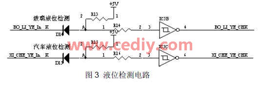
(3) Level charging protection circuit This machine consists of IC6 and P1 to form a battery floating charging circuit to ensure the reliable operation of the battery. P1 is the charging tube, its base is connected to the voltage overcharge switch, and IC6 is a two-way comparator. The battery charging range control circuit can obtain the reference voltage value of whether the DC 24V battery pack is overcharged on pin 6 of IC6. If overcurrent occurs, the voltage at this point will immediately stop charging. D1, D2, and D3 form a floating charge and voltage stabilization start circuit to ensure that the charging current to the battery is pulsating, and at the same time, IC17 and N2 form an overcurrent protection circuit to ensure that the battery is protected from overcharging. , To ensure the normal startup and operation of the whole machine. See picture 4 
4. Software part:
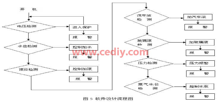
First, initialize the CPU control system. The purpose of the initialization is to restore some characteristic parameters of the system to the initial set values. At each stage, the key scan process is performed to see if the keyboard has any signal input. If there is input, the original state is updated and the corresponding data is sent according to the keyboard definition function requirements. Next, the power supply voltage is tested to determine whether the power supply voltage is correct and stable. If it is not correct, it will return to the power-on state immediately. If it is correct, it will enter the water level detection stage. Once the water level is insufficient, it is required to start the pump immediately. Add water while driving the buzzer to alarm. In the same way, the program goes to the next stage to determine the level of the car wash liquid and the glass liquid. First determine the level of the car wash liquid level. If it is not enough, start the water pump to add liquid. If the glass liquid is not enough, you need to start the liquid pump to add glass. Liquid, then enter the next stage is the pressure detection, first see if the steam pressure is enough, to meet (car wash requirements 6-8 ㎠/ ㎡), otherwise it is necessary to make the compressor work, at the same time start the pressure alarm to prompt the user, and then enter In the last stage of steam water level detection, first detect the water level of hot steam. If not, start the pump to add water to meet the user's requirements. After the completion, the system sets the timing for 10 seconds and then sends data to the beginning of the program to form a loop to complete the timing count and provide the system with a digital number. Due to the poor working environment of this machine, some anti-interference measures and means have been added to the software, such as the use of a watchdog circuit. When the program does not run on the original track and exceeds a certain time limit, the watchdog The dog circuit immediately generates a reset signal, forcibly resets the MCU, and restarts the program to avoid a crash. In addition, it is also possible to set up a “software trap†in the non-program area. When the program bounces into the software trap, the program will automatically execute the pre-programmed interference processing reset subprogram to reintroduce the program into the normal track. The software design flow chart is shown in Figure 5
Third, the circuit hardware design considerations and debugging methods I encountered the following problems in the actual design of the circuit need to pay attention to:
1. Due to the severe working environment of this machine, especially the interference to this system during ignition and vehicle start-up is very large, the hardware uses the anti-interference single-chip microcomputer STC89RC52 with excellent anti-interference performance, and the watchdog circuit and Various methods such as software traps are used to ensure the reliable operation of the circuit. In addition, some electromagnetic shielding measures are added to the processing of the circuit.
2. When simulating the wiring of signal circuits and digital signal circuits, it is necessary to separate them into independent wiring of the system.
3. The discrete components outside the module should use surface mount components to reduce the influence of lead distribution parameters.
4. When using modular design, pay attention to the analog and digital signals, high-frequency and low-frequency signals, the ground wire should be strictly separated, otherwise the circuit design will not work.
5. The electrical parts of the machine can be free of debugging. As long as the components are installed correctly and the wires are connected correctly, the machine can work normally, but pay attention to the wiring terminals. Never connect the strong and weak electrical terminals incorrectly to avoid damage to the machine.
4. Conclusion: With the continuous development of technology, steam car washers have been widely used in major auto repair plants, car wash shops, supermarkets, parking lots in residential areas, etc., providing safe, reliable and convenient for the majority of car owners Practical good equipment. At present, its technology is constantly improving, and it is rapidly developing in the direction of multi-function and intelligence.
Sixth, the author of this article innovation: it is a more comprehensive introduction to the design scheme of an electronic steam car washer circuit and the problems encountered in the implementation and solutions, highlighting the introduction of hardware working principles and software flowcharts, focusing on the introduction The working principle and technical solution of the detection and control circuit of the electronic steam car washing machine have wide practical value.
Safety: unlike glass neon tube, its normal operation requires a high voltage of 15,000V, while the flexible neon strip is at 12V. And its shockproof, temperature resistant, salt resistant, acid and alkali resistant.
Neon Christmas Lights,Led Neon Christmas Lights,Neon Word Lights,Christmas Neon Light Signs
Shenzhen Oleda Technology Co.,Ltd , https://www.baiyangsign.com