Raman crosstalk during the transmission of video services in a PON network
The G.983 series of standards describe a class of PON networks, which are based on wavelength division duplex and time division multiplexing technologies [1]. Usually people call these networks broadband broadband PON (ie BPON). BPON has the capability of digital transmission, with rates ranging from 155Mb / s to 1244Mb / s. These networks are the first to be defined as professional digital networks with two wavelengths: 1310nm for uplink and 1550nm for downlink.
Since the advent of the basic G.983.1 system, people increasingly understand that the video overlay service will become a valuable business. Since the video service is a broadcast service in the traditional sense, it is very practical and convenient to add a broadcast channel to the PON system. Later, the G.983.3 standard decided to use WDM technology [2]. The International Telecommunication Union (ITU) published the G.986.3 proposal to propose a broadband access system that improves service capabilities through wavelength allocation (see Figure 1). This proposal specifies the 1490nm wavelength for downstream voice and data signals, the 1550nm wavelength for downstream video signals, and 1310nm for upstream voice and data signals. The downstream digital emission wavelength range is generally very narrow, from the initial 100nm width to a smaller 20nm width with a center wavelength of 1490nm, while the upstream wavelength range is still within the 100nm region centered on 1310nm.
The new wavelength distribution scheme proposes a pair of applications called "increased bandwidth", including DWDM point-to-point coverage service and a broadcast video coverage service. The use of wavelength to complete the spread of the video service carried, however, this standard (G.983.3) does not specify the exact wavelength, power level and signal mode. Therefore, it is equivalent to say that the system supplier defines the signal parameters of the video service transmission.
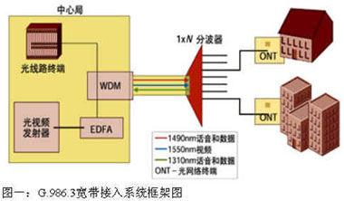
Taking all factors into consideration, the wavelength allocation scheme is the best. Many network equipment and device manufacturers have accepted ITU's G.983.3 recommendations. Therefore, many optical fiber network operators are installing such systems today. These systems are composed of optical line terminals (OLT), optical network terminals (ONT), WDM couplers, and 1 × N demultiplexers (Figure 1).
The "increased bandwidth" in the G.983.3 scheme is in the EDFA passband region from 1530nm to 1560nm, which allows the use of inexpensive amplifiers to cover the wavelength, which is particularly important for video transmission. Not only that, the G.983.3 standard can also form a wide protection band between the B-PON downstream wavelength and the coverage wavelength, making filtering and isolation easier.
In any case, any wavelength allocation plan will place two downstream wavelengths in the 150nm range, so that there is a Raman effect between each other. As a fact in the G.983.3 system, we will analyze how this effect actually affects the PON system.
2. Theory
The situation in the G.983.3 system is this: digital signals (1490nm wavelength, power approximately 0 dBm) play the role of Raman pumping of analog video signal wavelengths (C-band wavelength, power approximately 17 dBm). This effect has been formulated by Phillips [3]. The key result, the crosstalk rate (CCR), is expressed by Equation 1. Because the Raman effect has a low-pass characteristic, the lower the video channel performance, the worse the degradation.
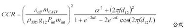
From Table 1 we can see the detailed parameter definitions. The effective modulation index mint of digital signals originating from an NRZ signal spectrum is expressed as:

It should be noted that Equation 2 is an approximate expression, rather than the exact same expression. Here, Equation 2 finds that the modulation index mint is exaggerated by a factor, so the CCR value (over 5dB) is overestimated. This can be confirmed by calculating the total digital signal power. we
It also proves that our formula 2 is correct, we will use this formula in the following calculations. Table 1 provides all used parameter values.
Table 1: Complete parameter list
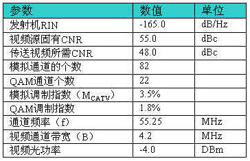
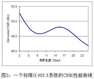
By giving these parameters, we can calculate all the CNR degradation caused to the analog video signal. It is very important to understand the relationship between CNR and link distance, because both received power and Raman interference have a great relationship with distance. The relevant results are shown in Figure 2. Here, a balance is reached between loss-induced degradation and Raman-induced degradation (degradaTIon). The figure shows that the CNR curve is relatively flat at the distance of interest, and it can be expected that the impact on the business is relatively small.
Where additional margins are required, there is a very simple way to reduce the impact of the Raman effect. Since Raman influence only exists in the low-channel domain, increasing the modulation index of these channels can get rid of the influence of Raman effect.
In North America, only channels 2 through 6 belong to the low-band region, and channel 7 is higher than 108 MHz, which is twice as high as channel 2. Therefore, channels 7 and higher are not affected by Raman interference.
3. Test
The performance of the G.983.3 coverage system has been verified in the laboratory by a commercial triplexer. The video transmitter includes a matrix generator that can generate 82 analog channels, a Motorola GX2 externally modulated 1550nm transmitter and an EDFA amplifier. The data transmitter is replaced by a 1490nm downlink transmitter in the QB5000 OLT (NRZ 622 Mb / s) QB5000 OLT (NRZ 622 Mb / s), which is a quantum bridge (Editor's Note: The company has been acquired by Motorola). Both transmitters use attenuators to control their output power to the required level, and then couple them into a single PON fiber, which is equipped with WDM devices. The fiber feeder (feeder fiber) is 10 kilometers long, very close to the fiber length corresponding to the worst case of the Raman effect. Connect a splitter at the output of the fiber, and then add an attenuator to control the video power transmitted to the ONT triplexer. In all cases, the analog video power is controlled at about –4.5 dBm, which is the most ideal sensitivity for the system.
CNR, CSO and CTB performance indicators are measured by selecting a channel in the entire band. In all cases, CSO and CTB are in the high 50 field, so there will be no distortion. The results of channel CNR measurement are shown in Table 2. There are four cases, the first case is to perform video operation under the condition that there is no data signal at all, and the performance of all channels is very good. Note that the very high channels are all below 48 dBc, but we found that this is mainly caused by the additional RF loss in the output section of the triplexer circuit, not the cause of the optical signal itself.
Table 2: CNR test results of G.983.3 system under four different conditions
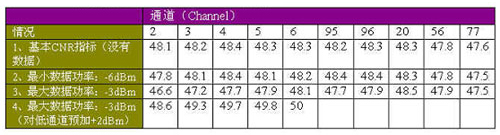
The second case is that the digital power is –6 dBm (the lowest in practical applications). Only channel 2 experienced performance degradation, and the other channels were still operating at a satisfactory 48 dBc CNR. When the fiber length reaches 10 kilometers, the Raman effect increases, which is theoretically expected. The third case is that the digital power is running at –3 dBm (the highest point in practical applications). In this case, we found that the low channels are severely affected by Raman crosstalk, and their CNR value also drops below 48 dBc . Note that this situation is worse than the worst-case scenario in reality. The worst-case scenario is that the video power at 10 kilometers is -2 dBm. In the course of this test, the video level (video level) is 2.5dB lower than what we actually measured in the field. Therefore, this test has certain practical significance.
The third case is similar to the fourth case, except that in the fourth case, those affected low channels are pre-compensated by 2dB. This increases the signal strength and restores the CNR values ​​of these channels to more than 48 dB. We noticed that this did not give the transmitter
Can cause undue influence. The fourth case finally proves that the G.983.3 system can still optimize the system performance by pre-emphasizing the low channel under the worst conditions.

Follow WeChat

Download Audiophile APP

Follow the audiophile class
related suggestion
Medical Device speaker is a kind of micro speaker unit which uses a diaphragm made of Mylar material. Mylar speakers are of ultrathin design and lightweight and clear voice. It is widely used in medical devices (sphygmomanometer, glucometer, fetus-voice meter-) .
There are two types of Mylar speakers from the shapes:
1) Round shapes, we have products from 10mm to 57mm in diameter.
2) Oblong shape, we have products in sizes of 1510/1712/1813-..


FAQ
Q1. What is the MOQ?
XDEC: 2000pcs for one model.
Q2. What is the delivery lead time?
XDEC: 15 days for normal orders, 10 days for urgent orders.
Q3. What are the payment methods?
XDEC: T/T, PayPal, Western Union, Money Gram.
Q4. Can you offer samples for testing?
XDEC: Yes, we offer free samples.
Q5. How soon can you send samples?
XDEC: We can send samples in 3-5 days.
Medical Device Speaker
Sphygmomanometer Speaker,Fetus-Voice Meter Speaker,Glucometer Speaker,Blood Pressure Monitor Speaker
Shenzhen Xuanda Electronics Co., Ltd. , https://www.xdecspeaker.com