In recent years, the application of high-brightness LEDs has developed rapidly, especially in signs and traffic lights. For automotive applications, LEDs are also very attractive. Long life, shock resistance, high efficiency, and good control of light sources are all its advantages. Of course, compared to incandescent lamps, LEDs require a driving circuit, and automotive electrical is powered by lead-acid batteries, which are charged by mechanically driven alternators. Such batteries are suitable for incandescent lamps, not LEDs. A drive circuit with good voltage performance and low noise is very necessary.
Theoretically, the LED light output is related to the drive current, but not to the power supply voltage. The most demanding applications, if the power supply voltage is stable, a resistor can limit the current. It is worth noting that for this simplest application circuit, the LED shows self-stabilizing characteristics to a certain extent. That is, if the temperature increases, the light output of the LED decreases, but at the same time its forward voltage drop also decreases, increasing the drive current, thereby compensating for the decrease in light output at higher temperatures. Unfortunately, the range of changes in automotive power supply is very large, between 8V-18V, the peak voltage can reach tens of volts. In addition, high-brightness LED drive current is large, will generate a lot of heat on the resistor, complicating the heat dissipation design.
The relatively simple solution is to use a linear buck regulator (Figure 1), D1 is a voltage regulator diode, the current through the LED is set to VD1 / RSET. D2 compensates the humidity of the base diode. This circuit still has the problem of energy loss and resistance heat dissipation. This circuit is a cost-effective solution for low-current LEDs, especially the forward voltage drop of LEDs in series and slightly lower than the power supply voltage. 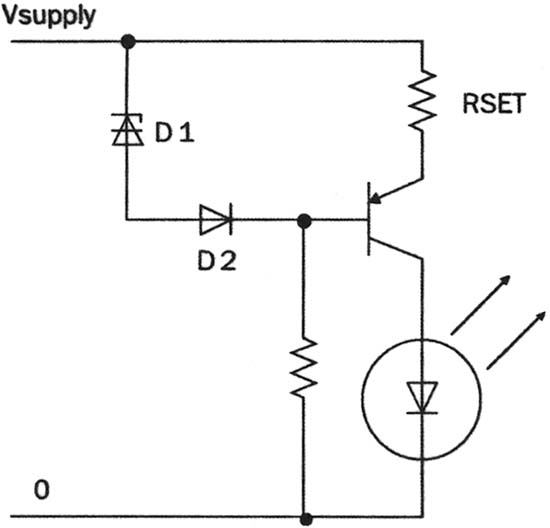
Figure 1 Simple steady current circuit
In most cases, switching power supplies provide a better electrical solution. As the name implies, the switching power supply works by switching. In one cycle, the RLC circuit is charged; in the next cycle, the stored energy is used to drive the load. This type of circuit is extremely efficient, generally reaching more than 90%. Switching regulators can boost voltages, lower voltages, and generate voltages with opposite polarities, which is not available in linear regulators.
The simplest switching regulator is the buck regulator shown in Figure 2. The voltage difference between the input voltage and the LED voltage charges the inductor L, and the current increases accordingly. When the current reaches a preset value, the control circuit Turn off the transistors in series to form an alternating current in the LED path. Note that in LED drive applications, the switching regulator circuit controls the peak value of the current. This value is set by the programmable IC or external components. The current value is also defined by the sense resistor on the drain of the FET switch. The current flowing through the LED of the buck regulator is continuous, but alternating, and discontinuous for the power supply. This will have a de facto effect on the power supply operation and also increase the noise on the power supply line.
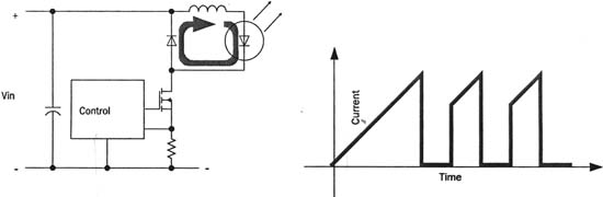
Figure 2 Step-down switching steady current circuit
If the power supply voltage is lower than the sum of all LED series voltages, a boost regulator should be selected. The boost regulator (Figure 3) needs to control both current and voltage, and the circuit is relatively complicated. The boost regulator also has serious interference problems under high current conditions. Therefore, the most stable and safest LED driver can use a combination of boost and buck. A boost regulator can drive several buck regulators in parallel. In this way, facing the power supply is a good performance boost regulator, and at the load end is a high current output buck regulator.
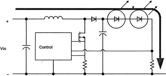
Fig. 3 Boost type switch steady current circuit
All switching power supplies will generate noise. Voltage regulators can increase the operating frequency and use a large capacitor to filter at the output. The LED power supply is stable. To reduce noise, the following measures must be taken:
· Reduce the working frequency.
· The switching transistor should be placed in the central area of ​​the circuit board.
· Fast recovery diode.
· Do not form a current loop in the LED area.
· Shorten the cables and traces on the printed circuit board.
In addition to the above measures, the new scheme also helps to reduce the noise of the driving power supply. Melexis' MLX10801 and MLX10803 LED drivers use a pseudo-random switching frequency generator to reduce electrical noise. Figure 4 is a circuit example of a low-noise application, which meets the CISPR25 level 5 standard, where CISPR is the French abbreviation for the International Special Committee on Radio Interference. The working inductance L1 should be determined according to the switching frequency and LED current. In order to facilitate user design, the company also provides a software and Excel table for selecting ROSC, RSET and RSENSE. For the circuit in Figure 4, the switching frequency should be less than 150KHz. If the LED current is between 0.5-1A, L1 and L2 are 100? H. The noise is broadband, so the filter capacitor uses a combination of large and small solutions. Diode D1 is the main source of high-frequency noise and should be selected carefully. When the power supply voltage is lower than 100V, a Schottky diode can be used.
The light output intensity of GaAs and GaAs PLED is closely related to the junction temperature. For example, if the LED outputs 100% at 25 ° C, it is only 80% at 80 ° C. The driver is equipped with a temperature slope compensation circuit. In fact, a PTC or NTC resistor can solve the problem, and the temperature coefficient of the PTC is used to balance the light output of the LED. To protect the LED, an NTC resistor can be added to the input of the device at temperatures above 80 ° C.
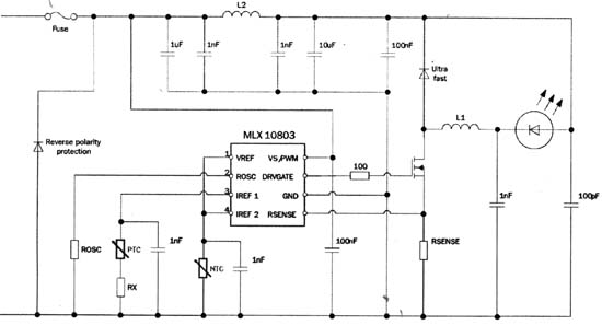
Figure 4 MLX10803 application example
Wooden USB Flash Drive and adorable, people put it down
1) can be designed according to customer requirements, production of various styles, various grades of wooden U disk enclosure.
2)
can be used according to the requirements of customers maple,
Paulownia, rubber wood, rosewood and other timber for making wooden USB Flash Drive enclosure. 3)
according to customer requirements using the traditional bite tenon
technique, bonding and other techniques for making wooden USB Flash drive
enclosure.
4),
according to the requirements of customers in the wooden usb flash drive
high-grade matte coating on the shell, semi-matte, crystal, food grade
non-toxic green paint and water paint.
5),
according to the requirements of customers on a wooden usb flash drive shell
screen printing, laser engraving a variety of text, graphics, company
logo and so on.
Wooden And Bamboo Usb Flash Drive
Wooden USB Flash Drive,Bamboo USB Flash Drive,Wooden USB Stick,Bamboo USB Stick
Custom Usb Gift company limited , https://www.customusbgift.com