2 System overall scheme The automobile dynamic weighing instrument mainly consists of the data acquisition module, the data processing module, the display module, the data communication module, the external memory and the external watchdog, as shown in Figure 1. The data acquisition module is responsible for amplifying, filtering and converting the weight signal detected by the weighing sensor into a digital signal and transmitting it to the CPU; the CPU is responsible for communication with various peripheral devices and analysis and processing of the weight signal, and sends the processed weight signal to Display module and communication module; the display module is responsible for the display of weight signals: the communication module is responsible for sending the weight signal to the host computer; the external memory stores the parameters of the instrument: the keys are used to set and modify the instrument parameters; the external watchdog is used to improve the instrument's Anti-interference ability, enhance the stability of the instrument.

3 hardware circuit design
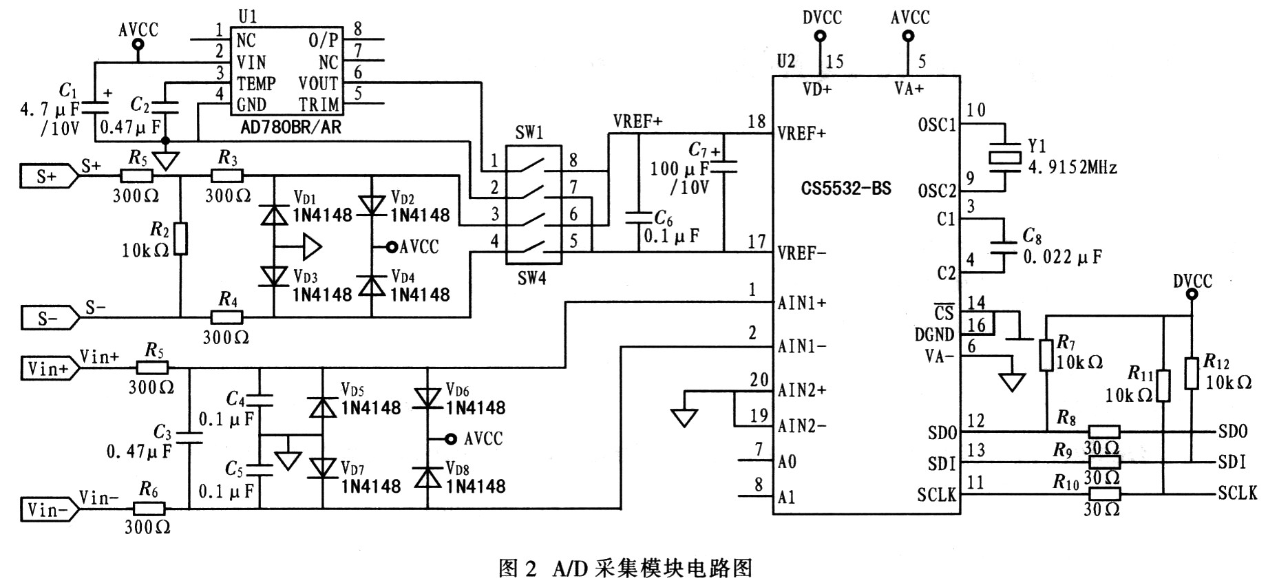
3.1 Data acquisition module Because the weighing instrument needs high precision, it uses external A / D converter and selects CS5532. The device is a multi-channel analog / digital converter with extremely low noise introduced by Cirrus Logic of the United States. Because it uses charge balancing technology and a very low noise programmable gain chopping stable measurement amplifier, it integrates amplification and internal The filtering function can get up to 24-bit resolution output, and has the advantages of high dynamic range and flexible power configuration options, making the device very suitable for dynamic weighing. The reference voltage is provided by a special reference voltage device AD780. The circuit is shown in Figure 2.
3.2 Microprocessor and external memory The microprocessor is the core of the system, and its performance directly determines the accuracy, stability and reliability of the weighing system. Based on the requirements of the automotive dynamic weighing instrument for accuracy and real-time performance, the P89C668 single-chip microcomputer of PHILIPS is selected. It has the following characteristics:
â‘ With 8 KB RAM and 64 KB Flash memory on-chip, this memory can be used for parallel programming or serial programming (ISP). In actual molding products, user programs can be upgraded by ISP; â‘¡The device is in 6 clock cycles One instruction is executed, which is twice that of the traditional 80C51; in each machine cycle, the speed is up to 20 MHz (equivalent to 40 MHz performance) under 6 clock cycles; The device has four 8-bit I / O ports, 3 16-bit timer / event counter, multiple interrupt sources, 4 priority levels, nestable interrupt structure, an enhanced UART and on-chip oscillator and timing circuit; these resources provide sufficient I / O for the hardware design of the system The port provides sufficient program storage space for the realization of software complex functions and future program expansion, and provides sufficient data storage space for the realization of weight data sampling, filtering and weighing algorithms, and can use ISP function to implement products Software upgrade.
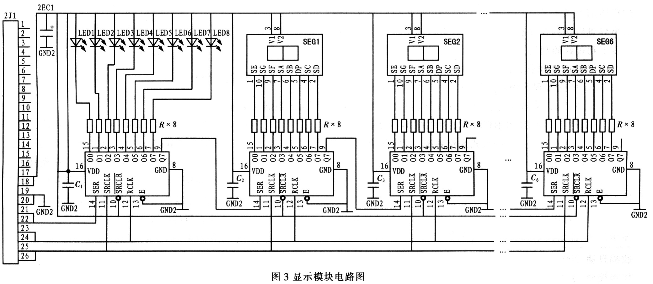
The external memory adopts AT24C512 device of ATMEL company, has 64 KB storage capacity, I2C interface, electrically erasable non-volatile EEPROM memory, provides storage space for setting and calibration parameters. 3.3 The display and communication module display driver uses SN74HC595, which is a serial input and parallel output shift register. Only 3 I / O port lines can be used to control 6 digital tubes and 8 light-emitting diodes, which greatly saves In view of the resources of the single chip microcomputer, the circuit is shown in Figure 3.
The communication module adopts MAX232 and adopts optical isolation design to improve the anti-interference ability of the instrument, as shown in Figure 4.

3.4 Keys and external watchdog circuit The keyboard uses a typical 4x4 matrix membrane key keyboard to set the instrument parameters. In order to improve the anti-interference ability of the instrument and enhance the stability of the instrument, an external watchdog reset circuit is used. The device chosen is MAX813, the circuit is shown as in Fig. 5.
4 System software design
4.1 Introduction to Small RTOS51 Small RTOS5l is an embedded real-time operating kernel designed specifically for 5l series single-chip microcomputers. Its code can be used directly using Keil compiler. Its features: ①open source code. As long as the license agreement is followed, anyone can obtain the source code for free, which is convenient for the user's secondary development. ② Portability. Users can compress control instructions related to the CPU to a minimum. Application programs can be written using ANSIC, which not only simplifies the programming method, but also facilitates program portability. ⑧ Curability. Small RTOS51 is an embedded system design that can be embedded in the product and become part of the product. ④ Preemptive operation. Small RT0S51 can manage 16 user tasks, each task can be set with different priorities. Small RTOS5l always runs the task with the highest priority. ⑤ Interrupt management. Use interrupt management. When there is a more advanced interrupt request, the task currently being executed is suspended. If the higher priority task is awakened by an interrupt, the high priority task will be executed immediately after the interrupt nesting ends. The number of interrupt nesting layers can reach 255. If necessary, nested management of interrupts can be prohibited. ⑥ RAM demand is small. SmallRTOS51 is designed for small RAM systems, so the demand for RAM is only a few hundred bytes, and the corresponding system services are also small.
4.2 System software implementation According to the functions to be achieved by the instrument, the entire system is divided into multiple parallel tasks, and the scheduling of tasks by the preemptive operation kernel is based on the priority of the tasks. Here the system is divided into 8 tasks, sorted in order of their priority from high to low. Use the task creation function OS-TaskCreate provided by the operating system to achieve.
(1) Task_AD is responsible for receiving the A / D converted data, that is, the sampling of the signal, and judging whether it is the automobile axle load data, if it is saved. Receive the data after A / D conversion through the interrupt service program, and send a semaphore AD_Sem after the reading is completed. After the Task_AD task receives the AD_Sem semaphore, it starts to judge whether to save the data. If the task detects that an axis has completely passed through the scale, it sends a message of the corresponding axis to the data processing task.
(2) Task_IdenTIfy is responsible for identifying the axle type of the car and whether the car completely passes the weighing platform. According to national regulations, cars with different axle types have different load limits, so when weighing dynamically, the meter should automatically identify the axle type of the car, and then judge whether it is overloaded according to the weight limit of the axle type car. The task also scans the signal of the vehicle separator to identify whether the vehicle has completely passed the weighing platform. If it is recognized that the vehicle has completely passed the weighing platform, the End_Sem semaphore is sent.
(3) Task_Comm_Rece is responsible for receiving commands from the host computer and responding to sending requests from the instrument. The instrument performs corresponding operations through different commands sent from the host computer.
(4) Task_Key is responsible for key scanning and identification.
(5) Task_Data is responsible for the processing of weighing data. When the task receives the axis information sent from the Task_AD task, it starts to process the axis data. The weight of the shaft is calculated by a weighing algorithm. And send the weight to the Task_Display task in the form of information.
(6) Task_Display is responsible for displaying weight and parameters. The task will receive the information from the data processing and display the weight of the shaft. If the instrument detects that the car has completely passed the weighing platform, the total weight of the car will be displayed. If the Task_Key task scans and the parameter key is pressed, it switches to the parameter display state.
(7) Task_End is responsible for a series of processing work after the car has completely passed the weighing platform, including total weight accumulation, axle group weight statistics, and axle type statistics. After processing, send information to the data communication information queue to notify the data sending task to send the corresponding data to the host computer.
(8) Task_Comm_Send is responsible for sending data to the host computer. When the task receives a communication message, it sends different data to the host computer according to different information values. For example, if the car is passing the weighing platform in the forward direction, the communication information value is 1. After receiving this message, Task_Comm_Send will send the weight information and axle type information of the vehicle to the upper computer. If the car passes through the weighing platform in the reverse direction, the value of the communication information is 0, and Task_Comm_Send will send the reversing information of the vehicle to the host computer after receiving this information.
5 Conclusion Using the embedded operating system as a development platform can improve efficiency, avoid complex loops and judgment structures in traditional development, and reduce the difficulty of program maintenance. The reasonable task division can meet the requirements of real-time, reliability and accuracy of the system.
LED street lamp refers to the street lamp made with LED light source, which has the unique advantages of high efficiency, safety, energy saving, environmental protection, long life, fast response speed, high color rendering index, and is of great significance to urban lighting energy saving.
Led Road Light,Led Off Road Lights,Led Roadway Lighting,Cob Led Road Light
Yangzhou Heli Photoelectric Co., Ltd. , https://www.heli-eee.com