1. Introduction The CAN bus is a communication protocol developed by the German BOSCH company in the early 1980s to solve the data exchange between many control and test instruments in automobiles. The CAN bus has been widely recognized and used in the industry because of its outstanding reliability, real-time performance and flexibility, and it became an international standard and an industry standard in 1993, known as "the most promising field bus" One. The application of the bus technology represented by CAN in automobiles not only reduces the body harness, but also improves the car's availability. In the design of modern modern cars abroad, CAN has become a must-have technology. Cars such as Mercedes-Benz, BMW, Volkswagen, Volvo and Renault all use CAN as a means of networking controllers. At present, there is a big gap in the application of CAN bus technology in automobiles in China. The research on the application of CAN bus technology in electric vehicles is still in its infancy.
Electric vehicles incorporate many electronic control systems, such as battery management systems, motor control systems, drive control systems, regenerative braking systems, and ABS systems. The large number of applications of electronic equipment will inevitably lead to the growth and complexity of body wiring, reduced operational availability, increased power loss on the line, and increased difficulty in troubleshooting. In particular, the introduction of a large number of electronic control units, in order to improve the utilization rate of signals, requires a large amount of data information to be shared among different electronic units, and a large number of control signals in the automobile integrated control system also need to be exchanged in real time. Meet this demand. The introduction of CAN bus technology into electric vehicles can overcome the above shortcomings and has broad application prospects. In this paper, the CAN bus technology is applied to the electric vehicle control system, and the universal expansion unit is used to solve the problem of the circuit design complexity of the electric vehicle electric control system, and the information of each electric control unit is optimized to achieve full information sharing to improve the electric vehicle control system. Performance purpose.
Second, the characteristics of CAN bus CAN belongs to the field bus category, is a serial communication network that effectively supports distributed control or real-time control. CAN bus is widely used in industrial control field thanks to its own technical characteristics.
(1) Only point-to-point, point-to-multipoint, global broadcast and other methods can be used to transmit and receive data through packet filtering without special "scheduling".
(2) Flexible communication methods. CAN works in a multi-master mode, any node on the network can actively send information to other nodes on the network at any time, without dividing the master and slave and without the node address and other node information.
(3) CAN uses non-destructive bus arbitration technology. When multiple nodes send information to the bus at the same time, the node with lower priority will voluntarily quit sending, and the node with the highest priority can continue to transmit data without being affected, thereby Greatly save the bus conflict arbitration time, especially in the case of heavy network load, there will be no network paralysis.
(4) The short frame format communication is adopted, the transmission time is short, the probability of interference is low, and it has an excellent error detection effect. The maximum number of bytes per frame is 8, which can meet the general requirements of control commands, working status and test data in the general industrial field. At the same time, 8B will not occupy too much bus time, thus ensuring the real-time nature of communication.
(5) Each frame of CAN information has CRC check and other error detection measures to ensure the feasibility of data communication.
3. Application of CAN bus in electric vehicles The application of CAN bus in electric vehicles has the following advantages.
(1) Reduce the number and volume of wiring harnesses required by each functional module.
(2) Reduce the quality of the entire vehicle and lower the cost of the vehicle, have higher data transmission reliability and ease of installation, and expand the functions of the vehicle.
(3) Some data such as vehicle speed, motor speed, and SOC can be shared on the bus, so redundant sensors are removed, the sensor signal lines are minimized, and the control unit can achieve high-speed data transmission.
(4) The function can be expanded by adding nodes. If the data expansion adds new information, only the software needs to be upgraded.
(5) Monitor and correct transmission errors caused by electromagnetic interference in real time, and store the fault code after detecting the fault.
Many existing automotive network standards have different functions. In order to facilitate research and design applications, the SAE Vehicle Network Committee divides automotive data transmission networks into categories A, B, and C3. Class A is a low-speed network for sensor / actuator control. The data transmission bit rate is usually only 1 ~ 10kb / s. Mainly used in electric doors and windows, seat adjustment and lighting control. Class B is a medium-speed network for data sharing between independent modules. The bit rate is generally 10 to 100 kb / s. Mainly used in electronic vehicle information centers, fault diagnosis, instrument display and airbag systems to reduce redundant sensors and other electronic components. Class C is a high-speed, real-time closed-loop control multiplex transmission network with a maximum bit rate of up to 1Mb / s. It is mainly used for suspension control, traction control, advanced engine control and ABS systems to simplify distributed control and further reduce the body Wiring harness. So far, only the CAN protocol is the only vehicle control local area network that meets the requirements of a Class C network.
4. Scheme design 1. System schematic diagram 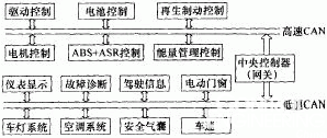
Figure 1 Schematic diagram of the system The system is mainly composed of drive control module, regenerative braking control module, motor control module, energy management module, battery control module, instrument display module and fault diagnosis module. Information communication between various control modules is realized through CAN. In addition to sending and receiving commands, some basic status information of the car (such as motor speed, battery charge state, vehicle speed, etc.) is the data that most control units must obtain. The control unit uses broadcast to send data to the bus. If all control units send data to the bus at the same time, data conflicts on the bus will occur. Therefore, the CAN bus protocol proposes bus arbitration that uses identifiers to identify data priorities. Table 1 shows the types of data received and sent by the electric vehicle electric control unit and the procedures for other units to share this information.
Table 1 Types of data received and sent by electric vehicle electric control unit
Note: T-send, R-receive 2. The block diagram of the module unit uses Universal Extension (UDU) when designing the nodes on the high-speed CAN. In this way, only by changing the software to achieve the different functions of each node, thereby simplifying the hardware system design. The structure of the universal expansion unit is shown in Figure 2.
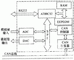
Figure 2 Universal expansion unit AT89C52 is used as the microcontroller in the universal expansion unit. It is a low-voltage, high-performance CMOS 8-bit single-chip microcomputer, which contains 8kB of repetitively erasable read-only program memory (EPROM) and 256B random. Access data storage (RAM), compatible with the standard MCS251 instruction system, built-in universal 8-bit central processor and Flash storage unit, can be applied to many more complex system control applications.
The CAN controller uses SJA1000 produced by Philips, which is an independent CAN controller used in automobiles and general industrial environments. It has all the necessary features required to complete the CAN high-performance communication protocol. The SJA1000 with a simple bus connection can complete the physical layer and All functions of the data link layer. It can store a complete message to be sent or received on the CAN bus. In addition, it has a 64-byte extended receive buffer REFIFO. The receive buffer is larger. While the microcontroller is processing a message, it can continue to receive other sent messages. Message. The bus transceiver uses PCA82C250, which provides a direct interface between the protocol controller and the physical transmission line, and can transmit data on two bus cables with differential voltage at a rate of up to 1Mb / s. The maximum number of connected nodes is up to 110. Using PCA82C250 can increase the communication distance, improve the system's instantaneous anti-interference ability, and reduce radio frequency interference. PCA82C250 and SJA1000 together constitute the control and interface circuit of the CAN bus.
5. Design of battery management and control system The battery is a key factor affecting the performance of the electric vehicle. It has a direct impact on the driving range, acceleration performance and maximum gradeability. The battery control system mainly monitors the working status of the battery (battery voltage, current and temperature), and manages the working status of the battery (to avoid over-discharge, over-charge, overheating and severe voltage imbalance between single cells) in order to maximize Use the storage capacity and cycle life of the battery. The structure is shown in Figure 3.

1) Real-time monitoring of the main and auxiliary batteries The UDU collects the battery voltage, current and battery temperature during the charging and discharging of the main and auxiliary batteries to monitor the working status of the battery and perform fault diagnosis.
2) UDU receives the vehicle driving status data from the bus and adjusts the motor speed and power output in real time according to the power requirements of the vehicle; when receiving the brake information, the control unit regulates the action of the inverter and the motor and starts the regenerative braking system to recover the brake energy.
3) Predict the remaining battery capacity and the corresponding remaining driving mileage. The control unit uses the corresponding algorithm to predict the remaining battery capacity using the collected charging and discharging current parameters. At the same time, the vehicle speed information received from the bus is used to estimate the remaining driving distance, and the estimation result is sent to the instrument display unit through the bus.
6. System availability design Due to the large temperature range (-45 ~ 100 ° C) in the car, strong electromagnetic interference and other electronic noise, and harsh environment, the network structure itself must be improved to ensure the system's availability in the car. Fault tolerance and anti-interference ability. In the design, anti-interference is carried out by a combination of software and hardware.
The hardware is designed with electromagnetic compatibility, focusing on dealing with the electrostatic field, magnetic field, and interference introduced by transmission lines and circuits. It uses filtering, decoupling, isolation, shielding, and grounding to add circuits such as power supply voltage detection and watchdog. The specific measures are as follows.
(1) The transmission line uses shielded twisted pair.
(2) Use the watchdog timer to perform timeout reset.
(3) An optical isolation circuit composed of a high-speed isolation device 6N137 is added between the CAN controller SJA1000 and the CAN transceiver PCA82C250, and the power supply is also isolated using a micro DC / DC module.
(4) Connect CANH and CANL of PCA82C250 to the CAN bus through a 5Ω resistor respectively, which can play a current limiting role and protect PCA82C250 from overcurrent impact. CANH and CANL are connected in parallel with a 30pF capacitor to ground, and the bus can also be filtered High-frequency interference on the Internet.
(5) Damage to the transmission medium or damage to the bus driver will destroy CAN * communication. If these failures cannot be automatically detected and corresponding measures taken to eliminate them, the system will even lose communication capabilities. The effective way to solve this problem is to use redundant communication control, so as to ensure the normal operation of the main functions of the communication system, so as to improve the reliability of the system.
The software uses error-tolerant and fault-tolerant technologies to filter the signal, design the power-on reset anti-interference program, and use real-effect insurance and other technologies to design the anti-instant interference program.
7. Conclusion The characteristics of the CAN bus and its application in electric vehicles are introduced. The node settings of the electric vehicle control system based on the CAN bus are designed, and the introduction of a universal expansion unit simplifies the system hardware design. The battery that affects the performance of electric vehicles The management control unit has been optimized. The system has the advantages of compact structure, high availability, perfect function and low cost, and can better meet the working requirements of electric vehicles.
1) Real-time monitoring of the main and auxiliary batteries The UDU collects the battery voltage, current and battery temperature during the charging and discharging of the main and auxiliary batteries to monitor the working status of the battery and perform fault diagnosis.
2) UDU receives the vehicle driving status data from the bus and adjusts the motor speed and power output in real time according to the power requirements of the vehicle; when receiving the brake information, the control unit regulates the action of the inverter and the motor and starts the regenerative braking system to recover the brake energy.
3) Predict the remaining battery capacity and the corresponding remaining driving mileage. The control unit uses the corresponding algorithm to predict the remaining battery capacity using the collected charging and discharging current parameters. At the same time, the vehicle speed information received from the bus is used to estimate the remaining driving distance, and the estimation result is sent to the instrument display unit through the bus.
I-Pulse Nozzle , in stock, original and new, fast delivery.The price is acceptable, service is guaranteed.
M1/M2:M001/M002/M003/M004/M005/M006/M013/M018
M018/N018/P018/K018
Characteristic:
1. Material: steel for body, durable for use;
2. Holder is made of china or tungsten steel;
M1/M4 series:
M001 LGO-M07701-00X
M002 LGO-M07703-00X
M003 LGO-M07705-00X
M004 LGO-M07707-00X
M005 LGO-M07709-00X
M006 LGO-M0770B-00X
M012 LGO-M0770E-00X
M013 LGO-M0770G-00X
M017 LGO-M0770H-00X
M018 LGO-M0770K-00X
M019 LGO-M0770M-00X
M020 LGO-M0770P-00X
M032 LGO-M0771K-00X
M2(N series):
N001 LC1-M7701-00
N002 LC1-M7703-00
N003 LC1-M7705-00
N004 LC1-M7707-00
N005 LC1-M7709-00
N006 LC1-M770B-00
N012 LC1-M770D-00
N013 LC1-M770F-00
N01 LC1-M770H-00
N018 LC1-M770K-00
N019 LC1-M770M-00
N020 LC1-M770P-00
N021 LC1-M770S-00
N022 LC1-M770PU-00
N032 LC1-M7714-00
Nozzles For I-pulse machine
Smt I-Pulse Nozzle
Fuji Nozzle
Smt Fuji Nozzle
SMT Nozzle
Smt Parts Nozzle
I-Pulse Nozzle
High Pressure I-Pulse Nozzle,I-Pulse Nozzle,Nozzles For I-Pulsemachine,Smt I-Pulse Nozzle
Shenzhen Srisung Technology Co.,Limited , https://www.sr-smt.com