Many people fail to grasp the distinction between signal grounding and power grounding, mistakenly believing they are one and the same. In reality, this article aims to clarify the grounding practices for various signals and the differences between signal grounding and power grounding. I hope this information proves useful to your learning.
**What is Signal Ground (SG)?**
The signal ground (SG) serves as the reference point for sensors measuring various physical quantities, the zero potential of signal sources, and the common reference ground (relative zero potential) for signals within the circuit.
Here, the term "signal" typically refers to analog signals or weak digital signals, which are prone to fluctuations in power supply or external factors, leading to a reduction in the signal-to-noise ratio (SNR). Particularly, analog signals can experience decreased SNR due to drift in the signal ground, resulting in measurement errors or system design failures.
Therefore, the requirements for the signal ground are stringent, necessitating special handling in the system to avoid direct connections with high-power power grounds, digital grounds, or easily generated interference grounds. For the measurement of small signals, the signal ground usually needs to be isolated.
**Main Purposes of Signal Circuit Grounding and Power Grounding**
Power supply grounding primarily serves to:
1. Ensure the safety of people and equipment, preventing electric shocks when insulation fails.
2. Meet system operational needs, such as the neutral point grounding of AC power systems or the positive or neutral grounding of DC power supplies.
The purpose of signal circuit grounding is to ensure a stable reference potential for signals. To maintain a uniform reference potential across electronic devices, avoid harmful electromagnetic field interference, and ensure stable and reliable operation, signal circuits in electronic equipment must be grounded, referred to as signal ground.
**Differences Between Signal Grounding and Power Grounding**
Power ground is primarily the path for power loop currents, with large currents flowing through it. Signal ground, on the other hand, serves as the return path for communication signals between two chips or modules, with very small currents flowing through it. Both are essentially GND, but the distinction lies in understanding their respective paths during PCB layout. When laying out the PCB, it’s crucial to clearly distinguish between power and signal return paths, avoiding shared return paths to prevent issues. Shared paths might cause large currents on the power ground to create a voltage difference on the signal ground (explained as: the wire has impedance, albeit small, but if the current flowing is significant, it still generates a potential difference, known as common impedance interference). This can elevate the true potential of the signal ground above 0V, leading to potential misjudgments if the signal ground's potential becomes too high.
Of course, power supplies are inherently unclean, and avoiding signal misjudgment due to interference is key. Paying attention to wiring can help mitigate these issues. Generally, even if they share paths, there won’t be major problems since digital circuits have high thresholds.
**Shielding Layer Grounding Methods and Principles for Signal Lines**
One end of a shielded wire is grounded while the other end is left open. When the signal line's transmission distance is long, differences in grounding resistance at both ends or current on the PEN line may result in differing potentials at the two grounding points. In this scenario, grounding both ends could cause current to flow through the shielding layer, potentially creating interference. Hence, typically one end is grounded while the other remains open to avoid such interference. Grounding both ends is preferable, but it can lead to increased signal distortion.
Please note: Two-layer shielding should be insulated from each other! If they aren't insulated, treat them as a single layer!
The outermost shield's grounding is caused by an induced potential difference, generating a magnetic flux that reduces the strength of the source magnetic field, thereby largely canceling the voltage induced without the outer shield.
The innermost shield is grounded at one end. Since there’s no potential difference, it's primarily used for general anti-static sensing. The following specifications provide the best proof!
"GB 50217-1994 Power Engineering Cable Design Specification" - Clause 3.6.8 states: The grounding method for the metal shield of control cables shall comply with the following provisions:
(1) The shielding layer of the analog signal loop control cable in the computer monitoring system should not form two or more points of grounding, and it is recommended to use centralized single-point grounding.
(2) For other control cable shielding layers that require grounding besides the (1) item and those with significant electromagnetic induction interference, two-point grounding should be used; for significant electrostatic induction interference, one-point grounding can be used. For double-shield or composite general shield cables, it is better to use one-point grounding for both the inner and outer shields.
(3) When choosing two-point grounding, consider that the shielding layer will not melt under the action of transient current.
"GB50057-2000 Building Lightning Protection Design Code" - Article 6.3.1 stipulates: ...When shielded cables are used, their shielding layers should be equipotentially connected at least at both ends. When the system requires equipotential bonding at only one end, two layers of shielding should be used, and the outer shielding should be handled as mentioned above.
The principle is as follows: 1. Single-layer shielding is grounded at one end, forming no potential difference, generally used for anti-static induction. 2. Double-layer shielding, the outermost shield is grounded at both ends, and the inner shield is equipotentially grounded at one end. At this time, the outer shield induces a current due to the potential difference, generating a magnetic flux that reduces the strength of the source magnetic field, thereby largely canceling the voltage induced without the outer shield.
If it is to prevent static interference, it must be grounded at a single point, whether it is one layer or two layers. Because single-point grounding discharges static electricity the fastest.
However, the following two cases are exceptions:
1. When there is strong current interference externally, and single-point grounding cannot meet the fastest discharge of static electricity.
If the grounding wire has a large cross-sectional area and can ensure the fastest discharge of static electricity, it must also be grounded at a single point. Of course, if that's the case, there's no need to choose double-layer shielding.
Otherwise, double-layer shielding must be used. The outer layer shielding is mainly to reduce the interference intensity. It is not to eliminate the interference. At this time, it must be grounded at multiple points. Although it cannot be finished, it must be weakened as soon as possible. Multi-point grounding is the best choice. For example, the cable tray in an enterprise is actually an outer shield. It must be grounded at multiple points, and the first line of defense reduces the intensity of the interference source. The inner shield (in fact, we don't buy double-layer cables, usually the outer layer is the cable tray, the inner layer is the shield of the shielded cable). It must be grounded at a single point, because the external strength has been reduced, discharge as soon as possible, and eliminate interference. It is the purpose of the inner layer.
2. Safety requirements such as external electric shock and lightning protection.
In this situation, two layers of protection are required. The outer layer is not used to eliminate interference. It is for safety reasons. To ensure personal and equipment safety, it must be grounded at multiple points. The inner layer is to prevent interference, so it must be grounded at a single point.
**Grounding Methods for Various Signals**
In addition to proper grounding design and installation, correct grounding of various signals is essential. In control systems, there are roughly the following ground lines:
(1) Digital ground: Also called logical ground, it is the zero potential of various switching (digital) signals.
(2) Analog ground: It is the zero potential of various analog signals.
(3) Signal ground: Typically the ground of the sensor.
(4) AC ground: The ground wire of the AC power supply, which is usually the ground where noise is generated.
(5) DC ground: The ground of the DC power supply.
(6) Shielding ground: Also called the chassis ground, designed to prevent static induction and magnetic field induction.
These ground wire treatments are an important issue in system design, installation, and commissioning. Here are some thoughts on the grounding problem:
(1) The control system should be grounded at one point. Normally, the high-frequency circuit should be grounded at multiple points, and the low-frequency circuit should be grounded at one point. In the low-frequency circuit, the inductance between the wiring and the components is not a big problem. However, the interference of the loop formed by the ground has a great influence. Therefore, the grounding point is often used as a grounding point; but one-point grounding is not suitable for high frequencies because the ground line has inductance, increasing the impedance of the ground line, and inductive coupling between the lines. Generally speaking, the frequency is below 1MHz, and one point can be grounded; when it is higher than 10MHz, multi-point grounding is used; one point can be grounded between 1~10MHz, and multiple points can be grounded.
(2) The AC ground and the signal ground cannot be shared. Since there are several mV or even a few V voltages between two points of a power ground, this is a very important interference for low-level signal circuits and must be isolated and prevented.
(3) Comparison of floating ground and grounding. The entire system is floating, that is, all parts of the system are floating with respect to the earth. This method is simple, but the insulation resistance of the entire system with respect to the earth cannot be less than 50MΩ. This method has a certain anti-interference ability, but it will cause interference once the insulation is lowered. Another method is to ground the case and leave the rest floating. This method is strong in anti-interference ability, safe and reliable, but it is complicated to implement.
(4) Analog ground. The connection of the analog ground is very important. In order to improve the anti-common mode interference capability, shielded floating technology can be used for analog signals. Grounding of specific analog signals should be designed in strict accordance with the requirements in the operating manual.
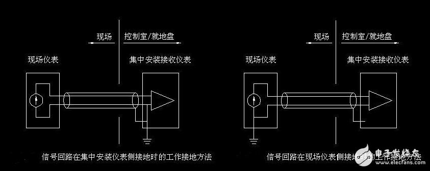
(5) Shielding ground. In the control system, in order to reduce the capacitive coupling noise in the signal, accurate detection and control, it is necessary to use shielding measures for the signal. Depending on the purpose of the shielding, the connection of the shielding ground is different. Electric field shielding solves the problem of distributed capacitance, generally connected to the earth; electromagnetic field shielding mainly avoids high-frequency electromagnetic field radiation interference such as radar and radio. Made of high-conductivity low-resistance metal materials, it can be grounded. The magnetic field shielding is used to prevent magnetic induction of magnets, motors, transformers, coils, etc. The shielding method is to use a high magnetic conductive material to close the magnetic circuit, generally it is better to connect the earth. When the signal circuit is grounded at one point, the shield of the low frequency cable should also be grounded at one point. If there is more than one shield location of the cable, a noise current will be generated, creating a source of noise interference. When a circuit has an ungrounded signal source connected to a grounded amplifier in the system, the shield at the input should be connected to the common terminal of the amplifier; conversely, when the grounded signal source is connected to an ungrounded amplifier in the system, the input to the amplifier should also be connected to the common end of the signal source.
For the grounding of electrical systems, it should be classified according to the requirements and purpose of grounding. It is not possible to simply and arbitrarily connect different types of grounding. Instead, it should be divided into several independent grounding subsystems, each with its common grounding point. Or ground the trunk, and finally connect together to implement the total grounding.
Cabinet charger, power solution, multiple devices,Mobile Bluetooth Charger
shenzhen ns-idae technology co.,ltd , https://www.best-charger.com