Convert 50Ω S-parameter to 75Ω S-parameter
Abstract: Cable TV integrated circuits are usually designed as 75Ω input and output impedance interfaces, while the impedance of most RF test equipment is 50Ω. In most cases, for testing purposes, a small loss attenuation network is used to convert the input and output impedance from 75Ω to 50Ω, or from 50Ω to 75Ω. Although this method is very convenient, you should avoid using small loss attenuation pads when measuring S-parameters. A simple way to make this kind of measurement is to treat the input and output impedance of the cable device as 50Ω, make the measurement, and then use the equations provided in this application note and the Excel spreadsheet to measure S based on 50Ω. The parameters are converted to S-parameters based on 75Ω.
Cable TV integrated circuits are generally designed as interfaces with 75Ω input and output impedance, while most RF test equipment uses 50Ω impedance. In most cases, a low-loss attenuation pad is used to convert the input and output impedance from 75Ω to 50Ω or vice versa. Although this method is very convenient, you should avoid using low-loss attenuation pads when measuring S-parameters.
This application note gives a simple method for S-parameter measurement. The input and output impedance of the cable device is regarded as 50Ω, and the measurement is performed, and then the mathematical transformation is performed. We provide equations and convenient Excel spreadsheets to convert S-parameters based on 50Ω to S-parameters of 75Ω.
Converting the S-parameter based on 50Ω to the S-parameter based on 75Ω starts from Equation 1. The S parameter and input impedance are complex numbers (R + jX), where R represents the real part and X represents the imaginary part. ZO is usually real impedance. For simplicity, this article only studies the input return loss (S11). 
Sort out Eq. 01 to get the expression Eq. 02 of the input impedance (ZIN). 
Replace S11 with R + jX. 
Multiply the complex conjugate of the denominator by the numerator and denominator of Eq. 03 to separate the real and imaginary parts. 
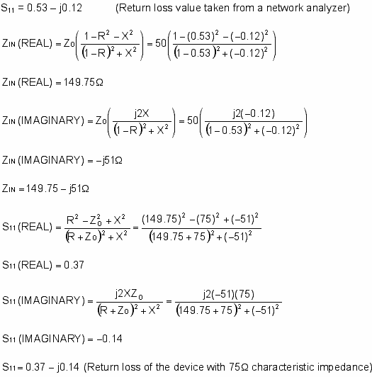
Eq. 06 is the real part of the input impedance. 
Eq. 07 is the imaginary part of the input impedance. 
After obtaining the complex input impedance, use Eq. 01 again to convert the impedance into an S-parameter referenced to 75Ω.
Eq. 08 is the same expression as Eq. 01, except that Z + is replaced with R + jX. 
Multiply the numerator and denominator of Eq.08 by the complex conjugate of the denominator to separate the real and imaginary parts. 
Eq. 11 is the real part of the input return loss (S11). 
Eq. 12 is the imaginary part of the input return loss (S11). 
example 
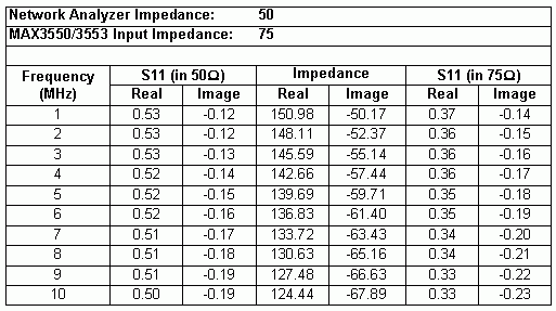
The Excel spreadsheet in Table 1 can help to quickly convert 50Ω S-parameters to 75Ω S-parameters. 
Electronic Burglary Safes
Electronic burglary Safes are safes that have passed Chinese 3C certification and use digital password lock systems.
Details:
They are convenient, safe and easy to use;
The safes provide high levels of security;
The Passwords can be changed easily to prevent theft and they`re also quite convenient for official usage because the personnel turnover in the office is normal, hence changing passwords is necessary;
3 times wrong passwords will cause alarm;
The emergency supply can be used when the electricity is off or in case of a black out or EMP Surge;
They possess elegant designs hence they not only provide protection but also serve as decoration pieces.
Electronic Mini Safe,Electronic Safe Box,Electronic Security Safe,Electronic Lock
YONGFA INTELLIGENT TECHNOLOGY SECURITY CO., LTD. , http://www.yongfa-safe.com